Simple DIY Off-Grid Solar System
Join us as we take a detailed walk-through of the planning and installation of our 3kW - 5kWH - 120V off-grid solar system that powers a rehabbed shipping container!
Hi there, we’re Jonathan & Ashley from Tiny Shiny Home. Our family of 6 spent many years traveling full-time in our renovated vintage Airstream before finding some off-grid property in Cochise County, Arizona to settle on.
Our dream here is to build a sustainable off-grid homestead from the ground up using solar power, water catchment, and natural building techniques to create an oasis in the desert.
If you’re looking for a safe, simple way to build a high quality DIY off-grid solar system that you can monitor remotely, you’ve come to the right place.
This isn't our first rodeo - we have a similar install video of our much larger, more complicated DIY solar system - it has 10kw of solar, 28kwh of lithium battery storage, and 5000w of 120V AC power. We’ll be referring to this project a lot as it informed a lot of the decisions we’ve made for this system.
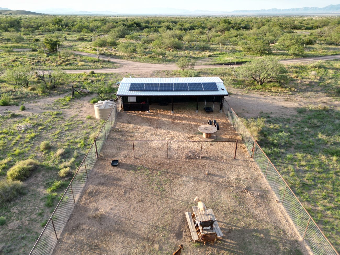
So when it came time to create power for our daughter’s goat barn container, we took all the lessons we learned from that much larger system to design a smaller, cheaper, safer, and more streamlined solar system.
Today we’re focusing on the planning, building, and installation process we went through to build this system, what it can do, and how much it cost.
Here are the high level specs:
- 3,000 Watts of Solar Panels (6S2P)
- 5kWH of LiFePO4 SOK Rack Batteries (48 Volts)
- 3,000 Watt Inverter (Single Phase @ 120V, Surge to 6,000W)
- All controlled with a Victron GX device for remote monitoring
- This should power a 40’ shipping container with lights, fans, fridge, water pump, and mini-split air conditioner.
Disclaimer: I’m not an electrician, nor do I play one on YouTube. All information here is solely for entertainment purposes, and all electrical work should be performed by qualified individuals according to local electrical codes. Cool? Cool.
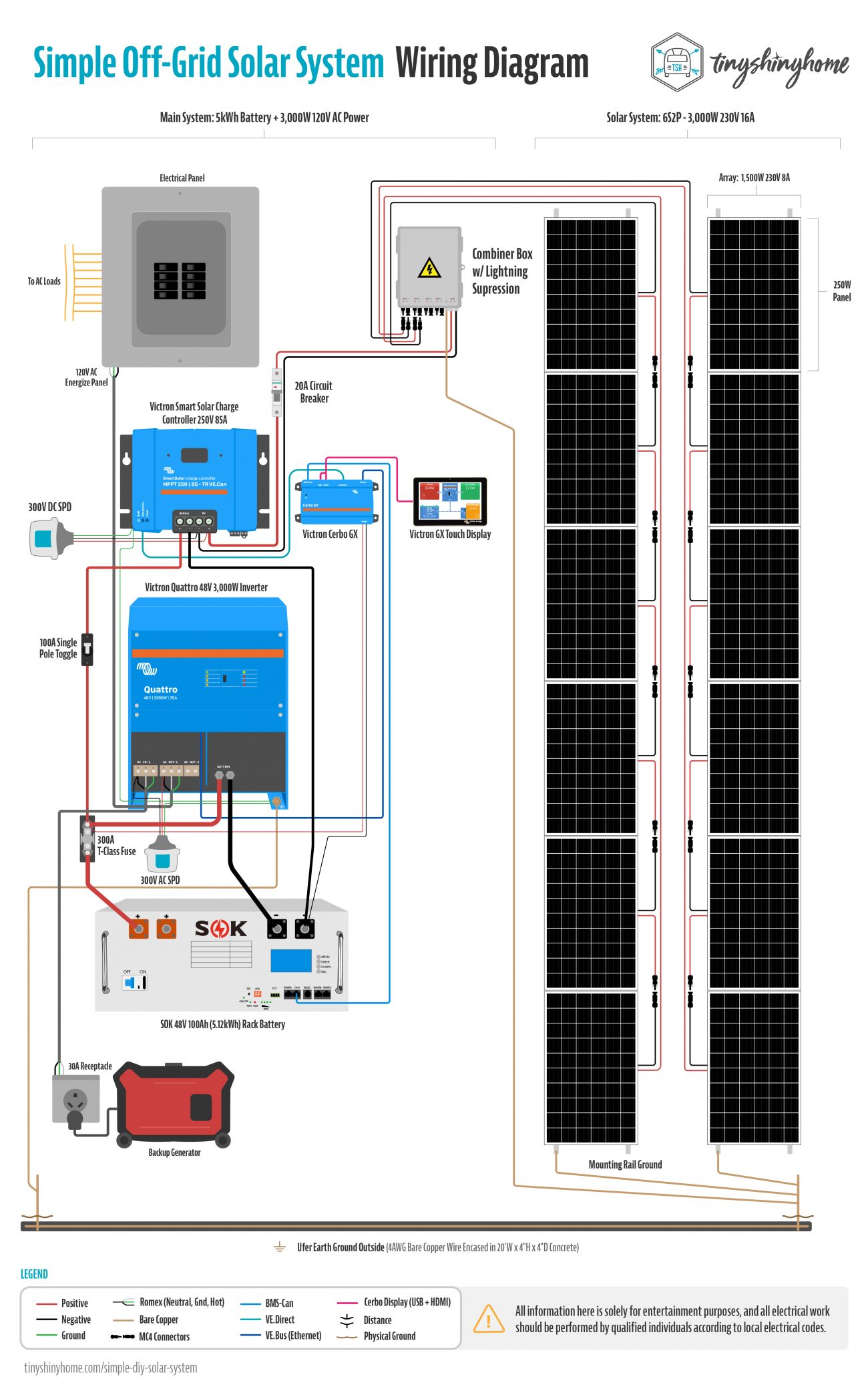
Ever wondered what all the major connections look like on a custom solar system like ours? As part of this deep dive, we created a very detailed replica of our wiring setup.
Now, if you read through this article we’re going to show you everything up close and personal, but if you’d just like to say thanks or you need a high res file you can download to study you can purchase the wiring diagram here:
Download Our Solar Wiring Diagram
Get up close and personal with this super detailed, impeccably illustrated hi-res PDF of our full off-grid power setup with a schematic representation of how everything in our 3kW, 5kWH, 120V off-grid battery and solar system connects together. Includes bonus individual component wiring configs, too!
Article Overview
- Purpose, Goals, and Sizing
- Why Victron
- Solar Roof Mounting
- Solar Wiring
- Victron SmartSolar Charge Controller 250V 85A
- Victron Quattro Inverter 48V 3,000W
- SOK 5kWh 48V Rack Battery
- Victron Cerbo GX
- Grounding the System
- Booting & Settings
- What to Expect
- Cost Breakdown
- Total
- Wrapping Up
Purpose, Goals & Sizing
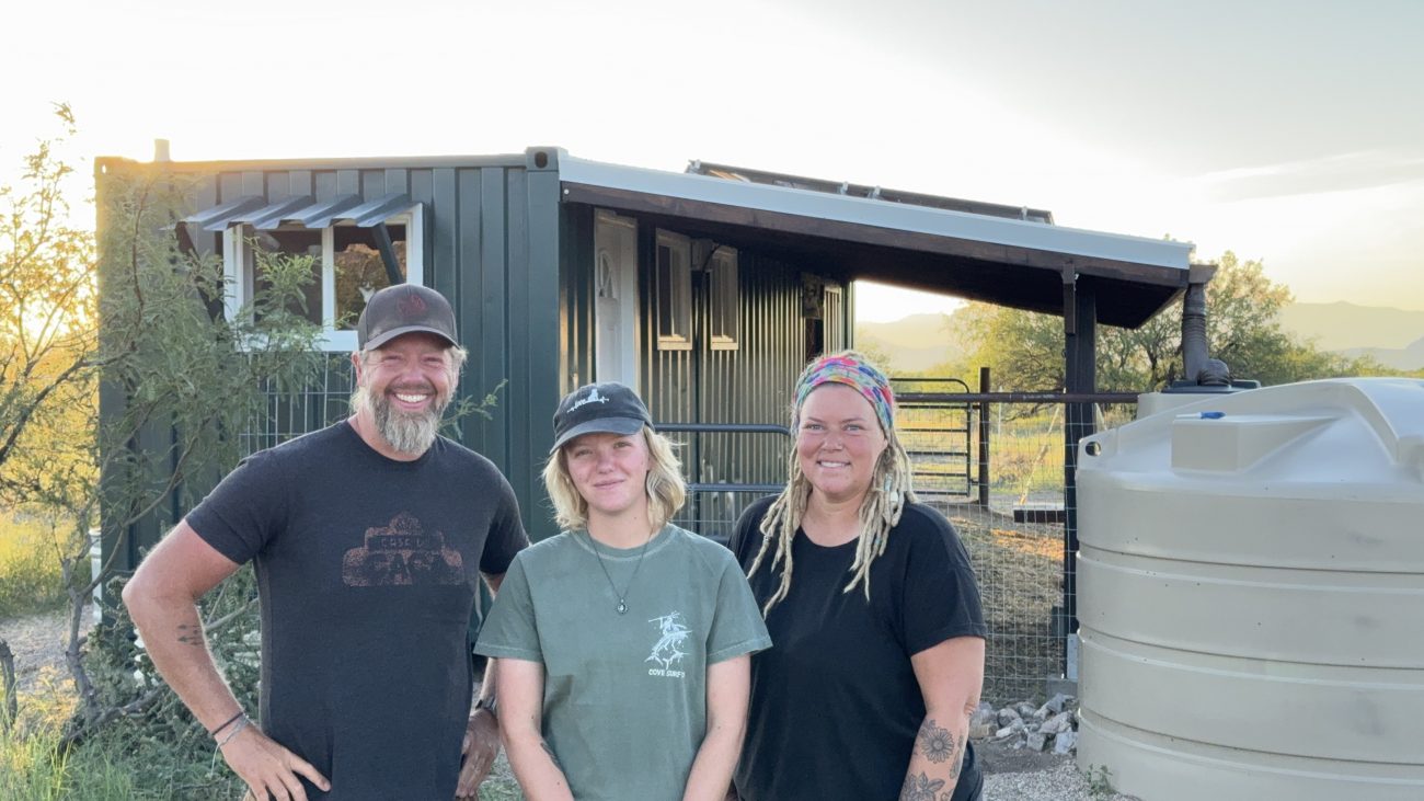
As with any good solar install, you gotta know what you’re building it for. This power system was part of a much larger project here on the homestead - rehabbing a used shipping container into our daughter’s dream goat barn.
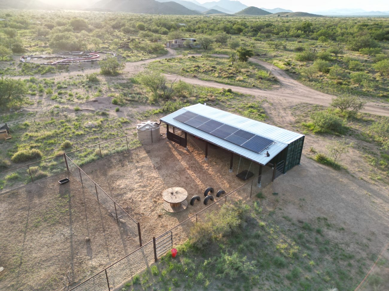
It included a fully renovated insulated and framed interior, modular kidding stalls, bulk feed storage, large shade awning roof, rainwater catchment, secure field fence paddocks, and a closed, climate controlled sanitary milking room.
Most of our power considerations were for the milking room. It housed a mini-split for heating and cooling, a fridge for keeping milk cold, and a small water pump for washing dishes and keeping the goats hydrated.
Not to mention lights, fans, cameras and other small draw items throughout.
Based on our experience with the larger install this is how we decided to size this new streamlined system.
3,000 Watts of Solar Power
By connecting 250w panels in series of 6 we could create high voltage arrays that charged well even in cloudy conditions and maximize the available space on the awning roof. We ended up with 12 panels total for this project.
5kWh Rack Battery Bank
In planning ahead for maintenance and modularity for our upcoming house system, we wanted to experiment with a different battery setup. To start we are trying a 5kWh SOK Rack battery to see how solid the BMS (Battery Management System) is, how it communicates with our Victron gear, and whether it is a better option than building our own bank. More on this later.
3,000 Watt 120V AC Inverter
Finally, the inverter. We didn’t need a lot of power, but we did want to focus on quality. We settled on a 3,000W Quattro Inverter Charger from Victron. The decision to go with Victron also tied into our charge controller, BMS, the ability to monitor the system remotely, and manage all power systems on the property from one app.
Why we’re a Victron Homestead
All the major components of this system are from Victron Energy. Why?
Because even though there are plenty of cheap all-in-one units out there, we think modularity and redundancy are important, that stable software is critical, and that supporting a small, passionate team of people who really care about this stuff is the way to go.
Victron has a wide range of options that are rock solid, take large loads like a champ, and can be monitored and controlled from anywhere in the world with internet connectivity.
And just so you know, we’ve never talked to Victron, and we’re not sponsored by them. After tons of research we made our own decision to use their products.
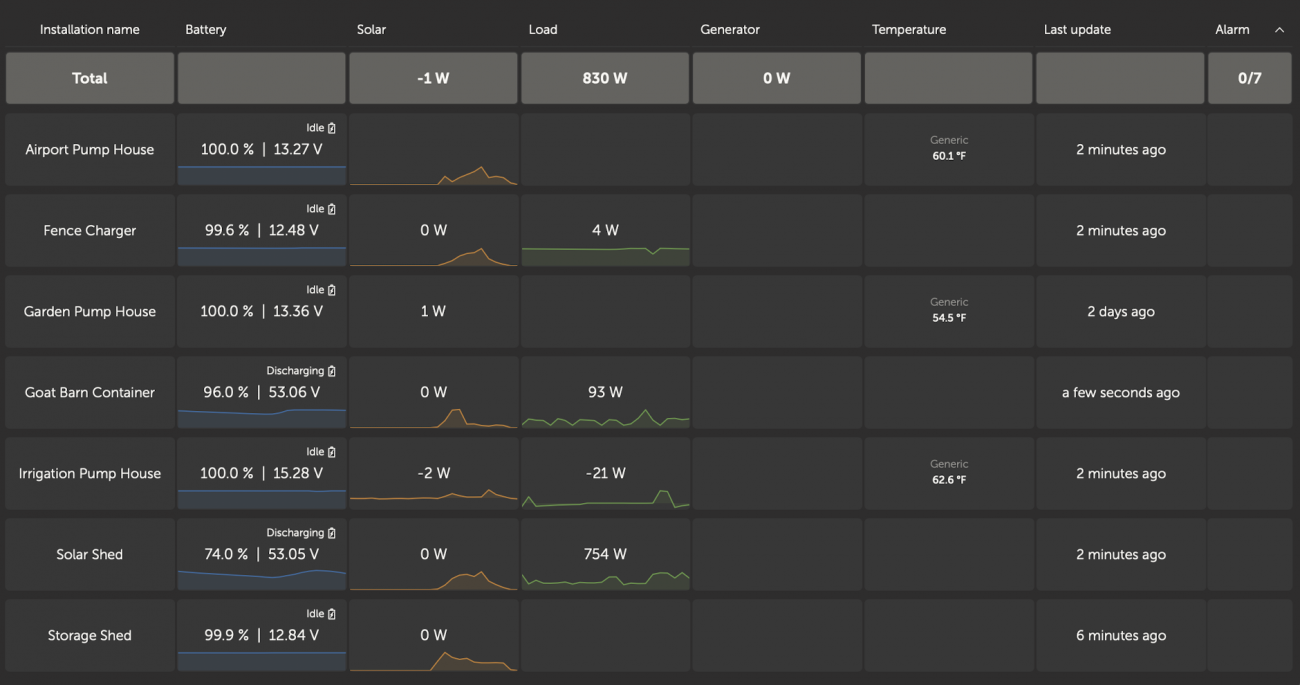
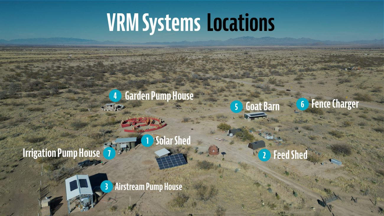
Right now we have 7 individual Victron installations running on our homestead ranging from large house sized systems to small 12v pump houses and remote fence chargers, and I monitor all of them from my phone without having to go walk 5 acres to get to them.
So we’re all in on Victron, and couldn’t be happier with how they’ve been performing over the years.
The modularity of a Victron system means we need a solar charge controller, an inverter, a shunt, and a GX device that will become the brain of the system. When connecting them all together (including the battery), they can intelligently communicate, adjust charging and protections, and relay all that back to the VRM (Victron Remote Monitoring).
Now that you know the basics of the system, let’s start building it.
Solar Wiring & Mounting
First our solar panels. If you’ve been watching us for a while you know we love SanTan Solar.
Here's a secret - solar panels in commercial installs get replaced often - usually way before they need to be. So SanTan buys them, tests them, and resells them to folks like you and me at a fraction of the cost of new ones.
They still have plenty of life left in them, and the cost savings can be so significant that even if they need to be replaced a few years earlier you're still getting a great deal. Solar panels don’t need to be fancy.
We grabbed a pallet of 30 250w snail trail panels for $1000 - so $33 each. We ended up using the extra ones to expand our big solar system to 10k watts (you can see that video here), but in case you were wondering, snail trails are just visual blemishes that don’t affect the output of the panel.
Our original solar project required a huge, expensive ground mount because we didn’t have any buildings or roofs to put the panels on. We used IronRidge to calculate and design the mount and have been really happy with their products.
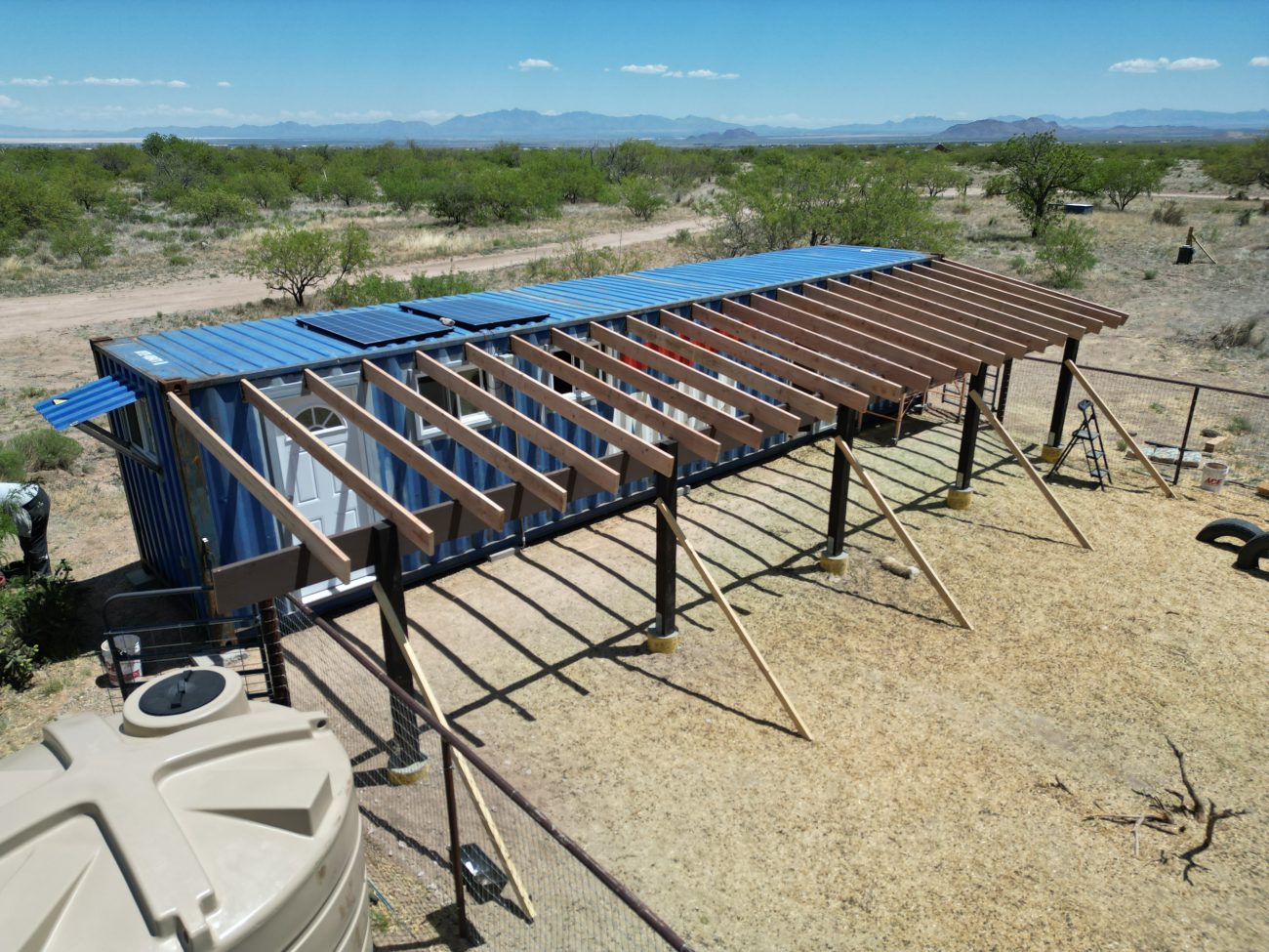
With this project, we added this shade awning roof off the south side of the container. It was over engineered because we knew we’d be using it to catch rainwater and put solar on.
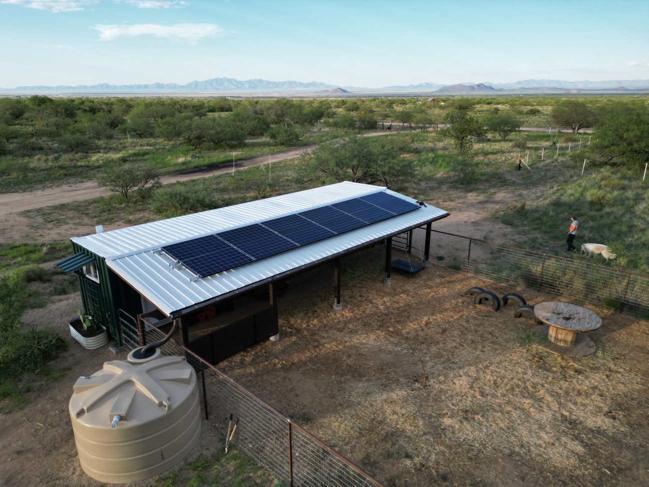
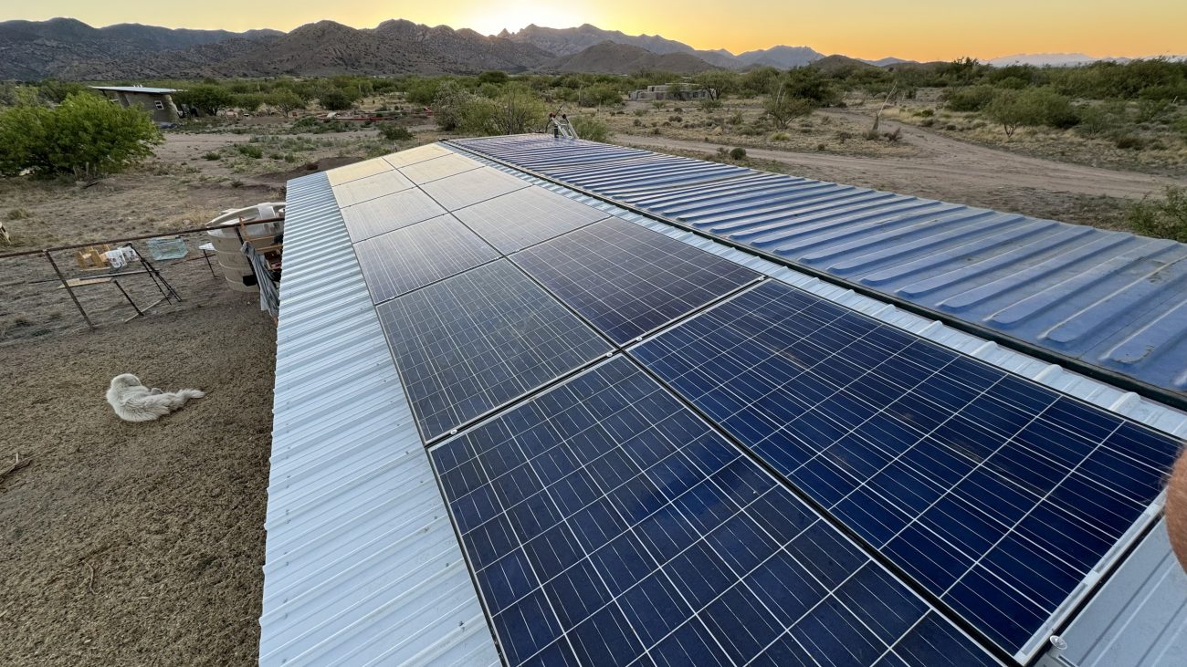
Based on the 40’x10’ dimensions of the awning, we settled on this horizontal configuration, cramming 12 panels up there for a total of 3,000 watts. And we did go back to IronRidge to design and build the roof mount system as well. We occasionally get hurricane force winds during monsoon season so being able to input all that data, the roof pitch, and material type were invaluable for making sure these stay secured during crazy weather events.
Since we were installing on a simple metal roofing R-Panel, we needed to first find a way to mount the IronRidge racking gear. The S5 Solar Foot turned out to be the best way to do this. It’s just a machined piece of metal with 4 screw holes and an 8mm stud and hex nut.
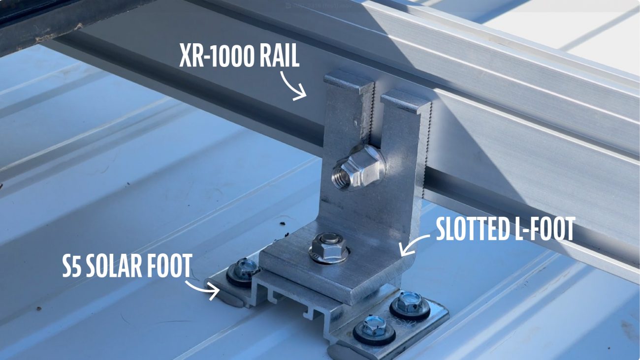
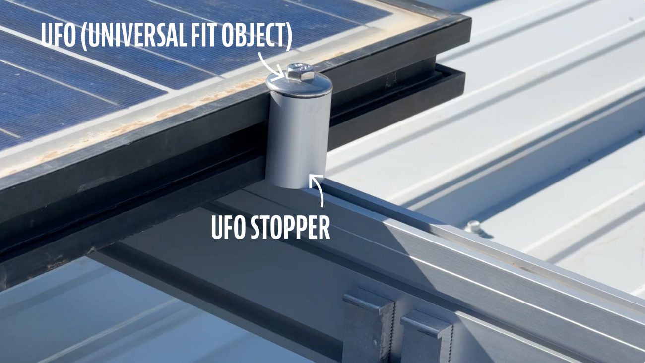
These are installed roughly every 4’, and then you bolt down IronRidge’s Slotted L-Foot, attach the main XR rail to that, and then use UFO’s or Universal Fit Objects to hold the panels in place.
A few important notes:
- On the first and last panel of the horizontal array you have to attach Stopper Sleeves to the UFO’s. This provides a solid, flat surface for the panels to sit against. Update: This has recently changed. Now instead of using UFO's and Stopper Sleeves get an EFO (End Fastening Object) for the ends.
- Set your first panel on the UFO’s then slide two more in the track so they touch the edge of the panel. Slide the next panel down on those UFO’s and repeat.
- You also need to tighten down the UFO’s to the correct torque. Too much and you could break the panel. Not enough and it might fly away in a wind storm.
- Speaking of torque, there are several parts of this process that require exacting torquing specs. I recommend getting both foot pound and inch pound torque wrenches as well as a deep socket set.
- This was really a pretty simple install - the hardest part was getting the Solar Feet spaced and lined up properly on the roof, and trying to get them to hit as many rafters as possible.
Wiring the Panels
With the panels installed, we turned our attention to wiring. Like we mentioned, our plan was to group 6 panels at a time in series to run at high voltage. This meant the panels would produce more power earlier and later in the day or in cloudy conditions. Connecting in series combines the voltage of each panel, and connecting in parallel combines the amps of each panel.
Here's how the math worked out.
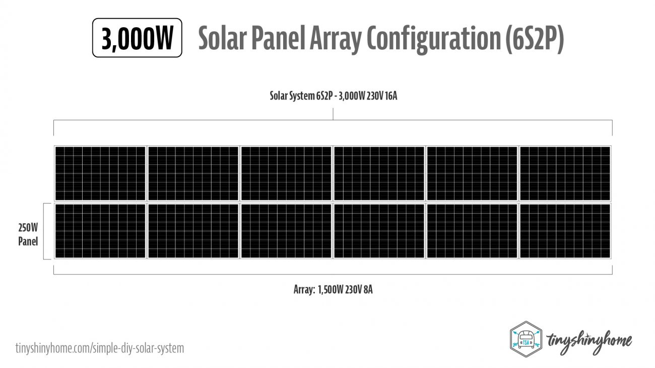
Each 250W solar panel (37V, 8A) connected 6 in series produced an array with 1,500 Watts, 230 Volts, & 8 Amps. Then connecting both arrays in parallel created a 3000W, 230V, 16A solar panel system.
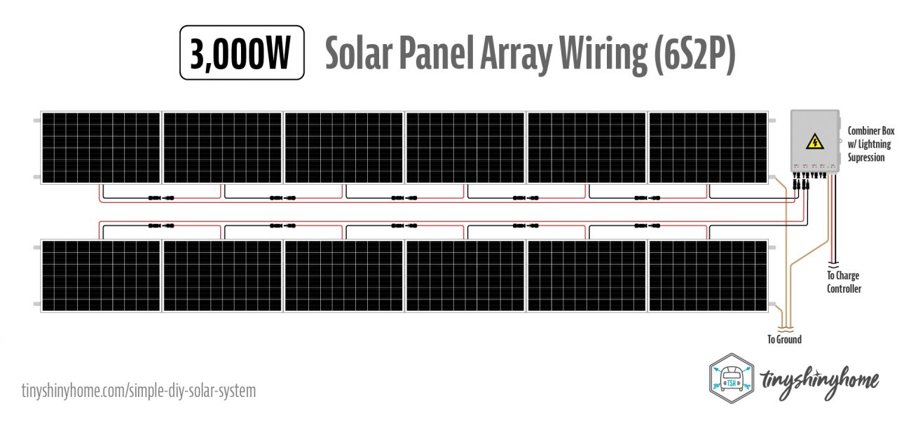
When connecting in series, you take the positive of the first panel and connect it to the negative of the second panel.
Then the positive of the 2nd panel to the negative of the 3rd panel, and so on down the line. This means that each panel adds an additional 37 volts for a total of nearly 230 volts.
If you started with positive, then your last panel will use the positive wire to go to the positive string input on the combiner box, and back at the first panel where there’s an empty negative you will need to extend back to the combiner box.
This meant buying our own MC4 connectors, and about hundred feet of PV solar wiring.
We mounted a heavy duty combiner box on the outside of the container, and connected the positive and negative of the first array to the first input, and the positive and negative of the second array to the second input.
This paralleled the two arrays together into the full 3,000w, 230v and 16 amps. Out of the combiner box we ran 8AWG wire inside the goat barn to the system.
Both the IronRidge rack and the combiner box need to be earth grounded, but we’ll come back to that later.
Warning!
We're officially moving into the "wiring everything up stage." Please keep a few things in mind:
- While connecting your system make sure everything is off. The breakers in the combiner box, all toggle switches, the battery, etc…
- Do your best to run all positives together and all negatives together so that you’re completing the circuit at the last step.
- ALWAYS cover your battery posts so you don’t short anything with an accidental tool drop.
- Make your connections and we’ll go through the boot up process at the end.
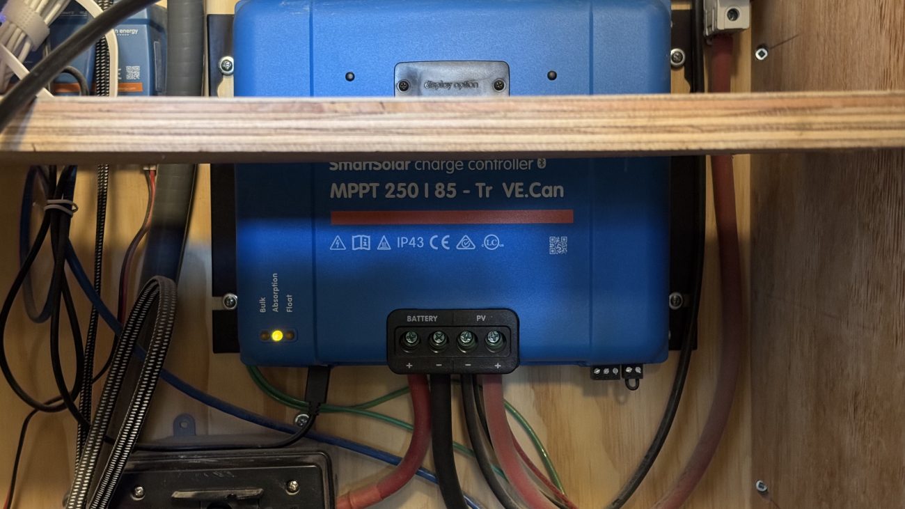
Victron SmartSolar MPPT Solar Charge Controller
From the combiner box, that 8AWG wire will connect to the PV positive and negative on the Victron SmartSolar 250V 85A Charge Controller. But the positive line should run through a 20amp circuit breaker first. This adds additional protection should the breakers in the combiner box fail, and a way to shut off solar power from the inside if we need to work on the system.
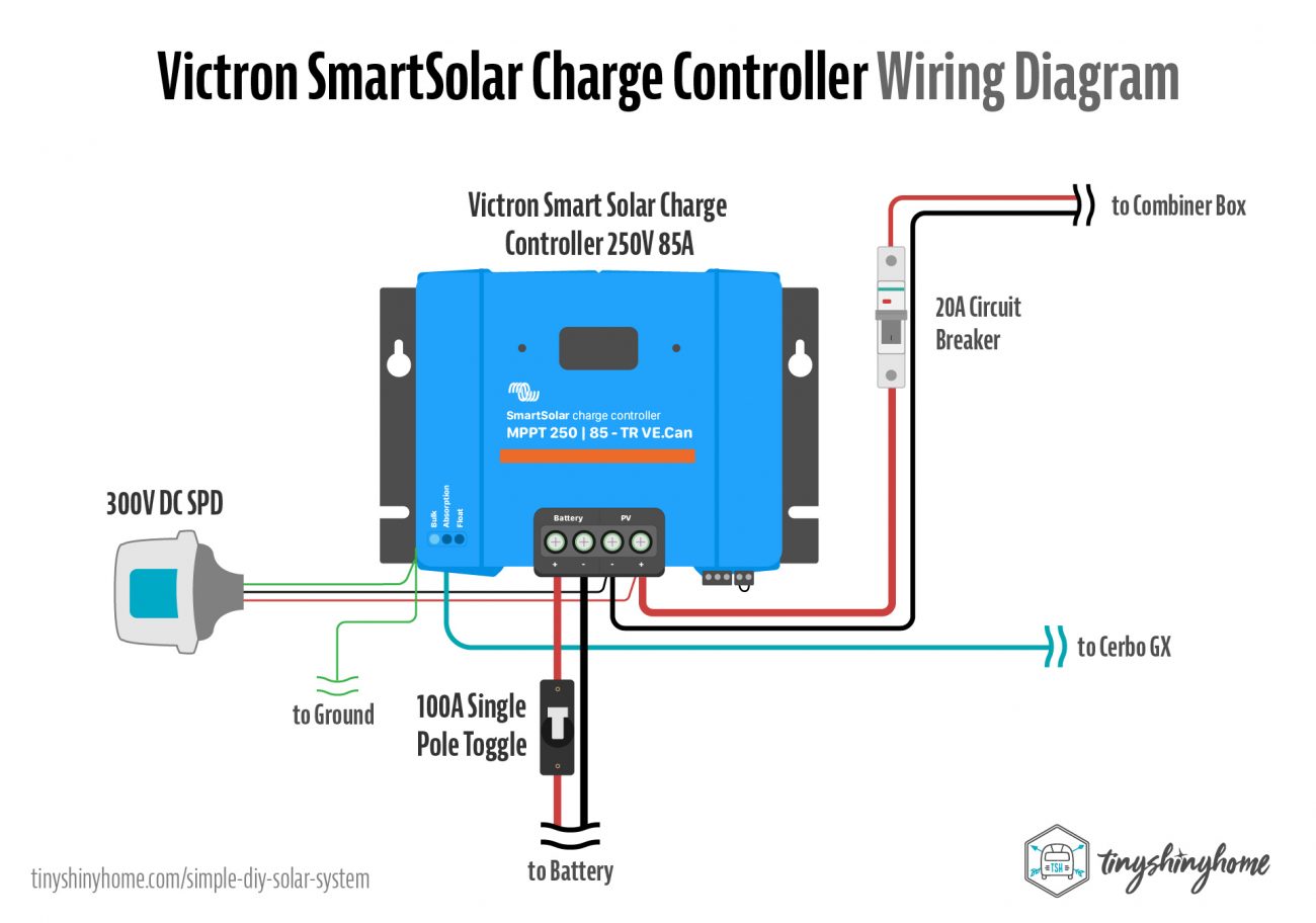
While we’re here, go ahead and install a DC Midnite Solar Lightning SPD into the positive and negative PV connections as well.
The ground from the SPD and charger chassis will go to a single earth ground which we’ll explain later.
Then the battery positive connection uses 2 AWG welding wire with crimped ring lugs that flows through a 100A Single Pole Toggle - this acts as even more protection for the batteries and system as the power coming out of the MPPT charge controllers is higher than what the panels are putting in. MPPT is cool like that.
Coming out of the toggle, the battery positive wire will continue to the System side of the T-Class Fuse holder. We’ll cover the T-Class more in the battery section.
The battery negative connection also uses 2 AWG welding wire and will connect to the negative side of the battery.
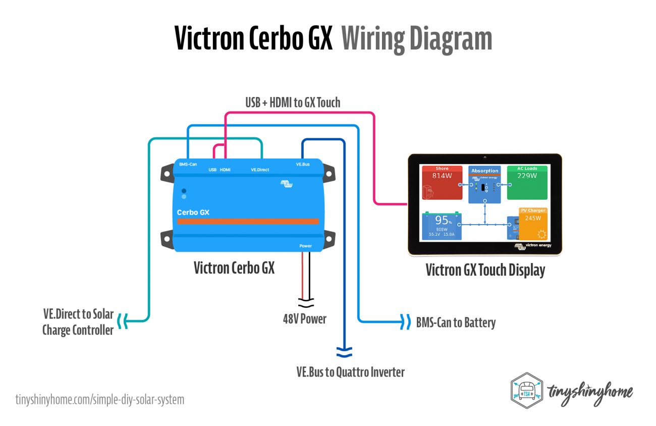
Don’t forget to run a VE.Direct Cable to the Cerbo GX for communication.
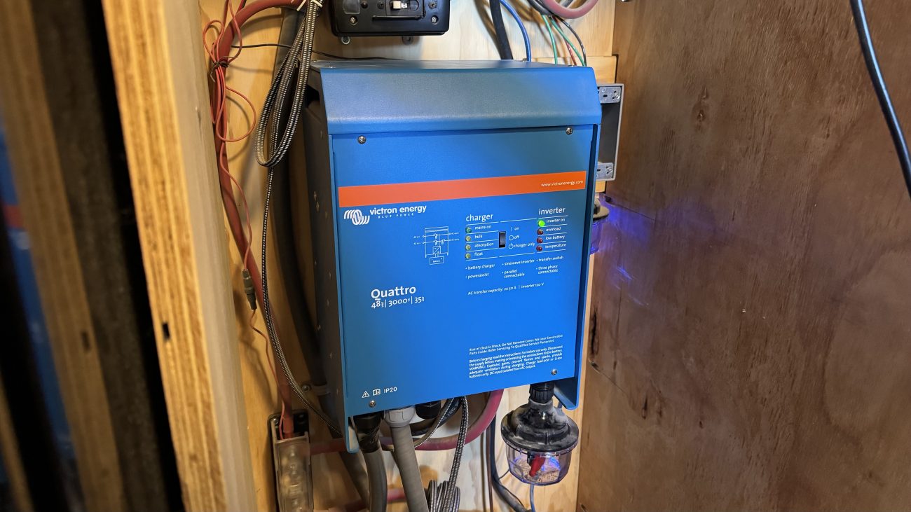
Victron Quattro 48V 3,000W Inverter
Next up is the Inverter. From the System side of the T-Class Fuse holder run a 2/0 AWG welding cable cut to size with crimp lugs to the battery positive on the Quattro. Then run the battery negative directly to the negative post on the battery.
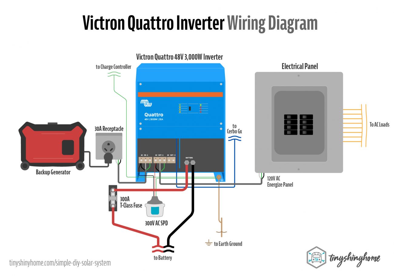
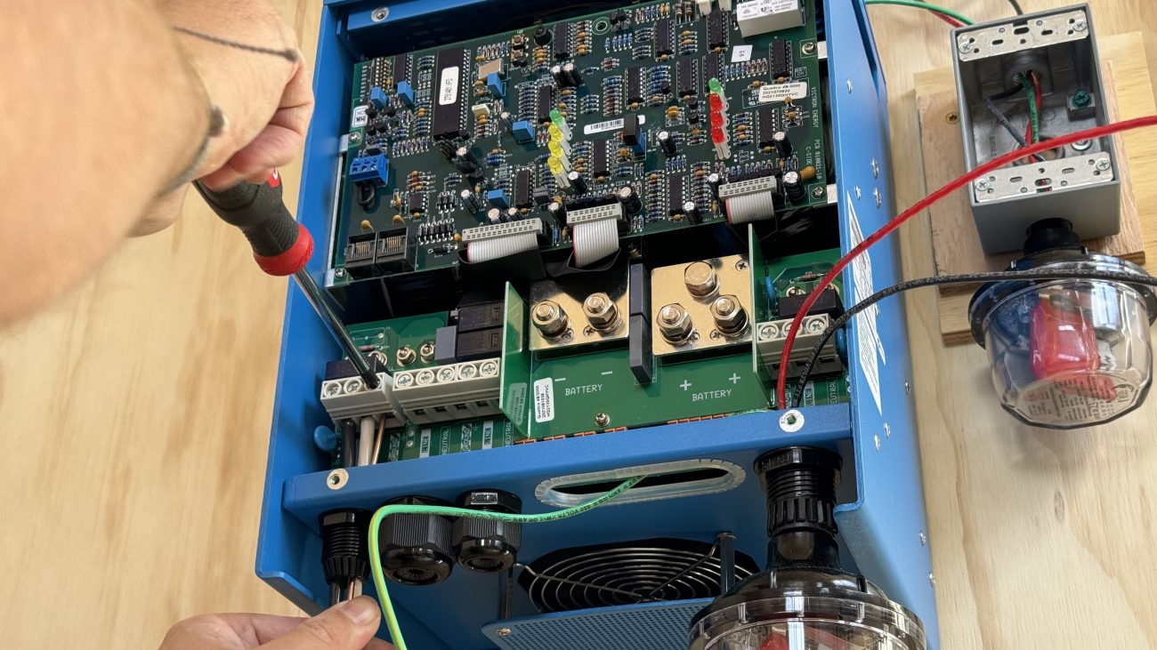
On the AC side, run your hot, neutral and ground out of AC Out-1 into your main breaker box where you’ll connect AC loads. These should be 8AWG or 6AWG.
If you want to put in a generator backup, run a hot, neutral, and ground from AC In-1 to the power inlet box. These should also be 8AWG or 6AWG depending on how big your generator input will be.
While you’re here we recommend installing a Midnite Solar AC Lighting SPD. One leg will go to the hot on AC In-1, and the other will go to the hot on AC Out-1.
The 3,000W version of the Quattro is different than my 5,000W. There is no designated “earth ground lug” - all the grounds seem to be bonded to the chassis.
Anywhere you have an AC connection use the ground provided, and for everything else run it to the chassis ground lug on the bottom of the case.
So the SPD ground should connect there along with the charge controller grounds and main earth ground wire to the outside. Again we’ll go deeper on grounding in a bit.
Finally, run a VE.Bus or Ethernet cable from the Quattro to the Cerbo GX.
Hey we’re almost there! Let’s connect the battery.
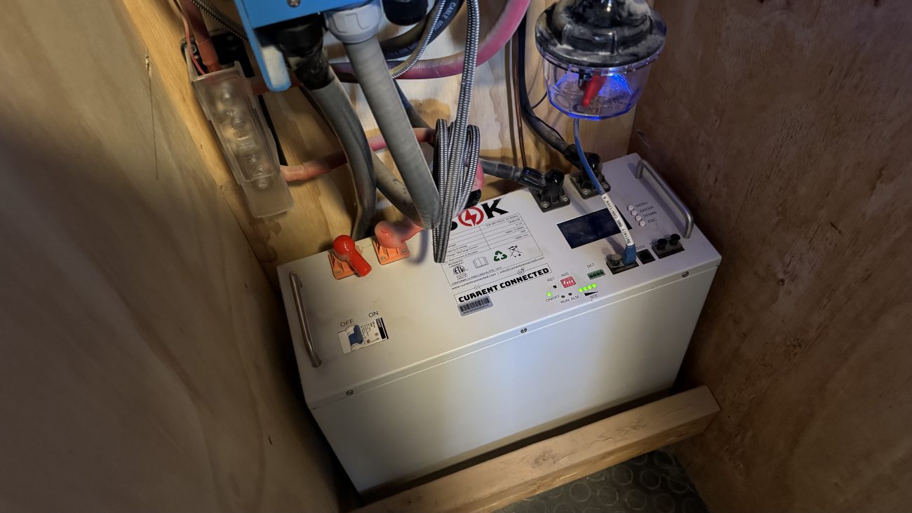
SOK 5kWh 48V Rack Battery
In our big system we bought individual cells directly from China and pieced together the battery bank ourselves using copper bus bars, a custom metal frame, and bespoke BMS (Battery Management System).
This saved us a ton of money, especially for a system of that size, but we didn’t need anything near that big for the goat barn. In fact, buying our own BMS and building a pack of only 5kWh was kind of cost prohibitive.
While I’m glad we went through the process of building our own bank, we’re also thinking long term about maintenance and modularity in our upcoming hyperadobe roundhouse system.
For example, since that original 28kwh battery bank was made out of individual 3.2v cells to get to 48v - if one or two went bad the only way to service them would be to pull the whole battery bank apart. See diagram below:
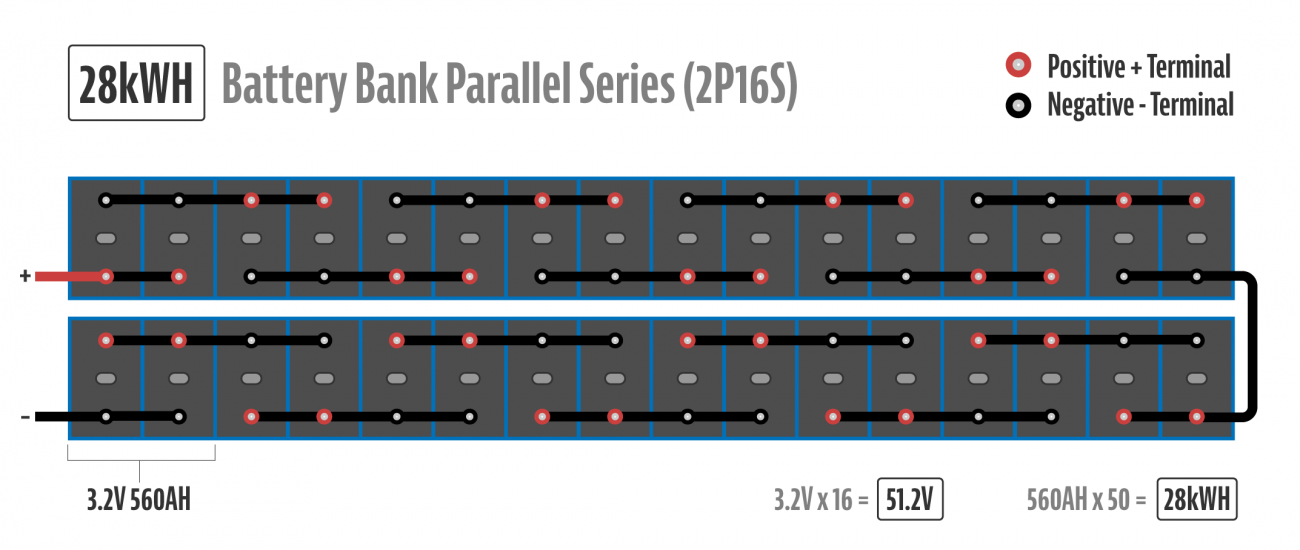
That would mean decompressing them, removing the copper bus bars, and even if we wanted to temporarily put it all back together without the bad cells it wouldn’t be a 48v pack anymore. Which means the inverter and charge controller would just throw low voltage errors and nothing would work.
So we thought we’d try rack batteries. While rack batteries are more expensive, they generally come in 5kwh self enclosed mini 48v systems that can be paralleled together. So if I had 6 racks totaling 30kwh, and one needed to be worked on, I could simply pull it out, my voltage would stay the same, and my kWh would be reduced down to 25kWh while staying the same voltage.
The other potential upside is that the BMS is built in. While our REC BMS is very configurable and takes good care of our batteries, it was so complicated and expensive to install. Being able to just plug and play the battery into the Victron ecosystem sounded nice.
Of course that all depends on whether the BMS is actually any good.
Rack batteries are quickly becoming a mature market here in 2024 so there are a number of them to choose from. The most popular are probably the EG4’s and SOK’s. I know some people personally that have had issues with their EG4 gear so because of that we decided to try the SOK 5kWh 48V Rack Battery for this project.
SOK’s have a pretty good reputation for talking directly to Victron equipment via the BMS Can Bus, being user serviceable - i.e. you an open them yourself and replace components - and being sturdy and well-built.
Also, since the housing has a BMS and circuit breaker switch built-in, it means we can drastically simplify our system.
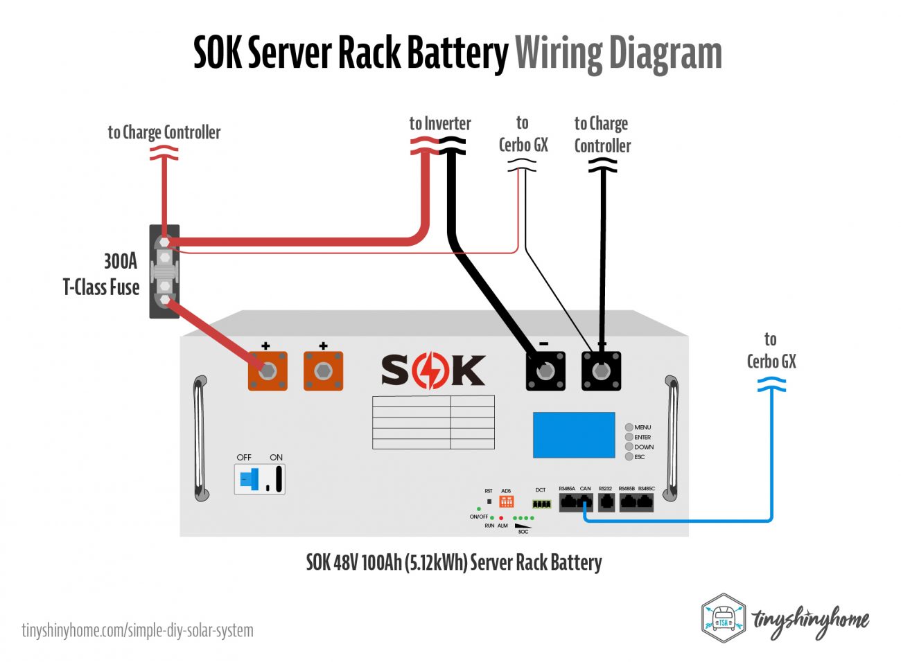
So back to wiring it up - we’ve already connected several items to the battery, but the most important is to run a 2/0 Welding wire and crimped lug from the other side of that T-Class Fuse Holder to the actual positive post of the battery. As long as the battery is off, you can also install the T-Class fuse in the holder at this time.
The idea behind the T-Class Fuse is that during an unwanted power surge event, it will blow and break the main connection to protect your equipment. It should be placed as close to your batteries as possible.
Believe it or not, there’s only one more wire for the battery. You’ll need a special BMS-CAN Type A Cable to connect from the Can port on the SOK battery to the BMS-Can on the Cerbo GX.
One last benefit of the rack battery is that in a system this small it can act as the shunt reporting the SOC, voltage, and more without needing to purchase an additional Smart Shunt from Victron. Nice!
Cerbo GX
And finally - even though we’ve run most of the wires to the Cerbo GX, we do need to power it. So run the positive wire to the system side of the T-Class Fuse, and the negative side to the negative post of the battery. We are using a GX Touch 50 screen which plugs into the HDMI & USB Power port on the Cerbo so you can do that as well.
Grounding the Off-Grid System
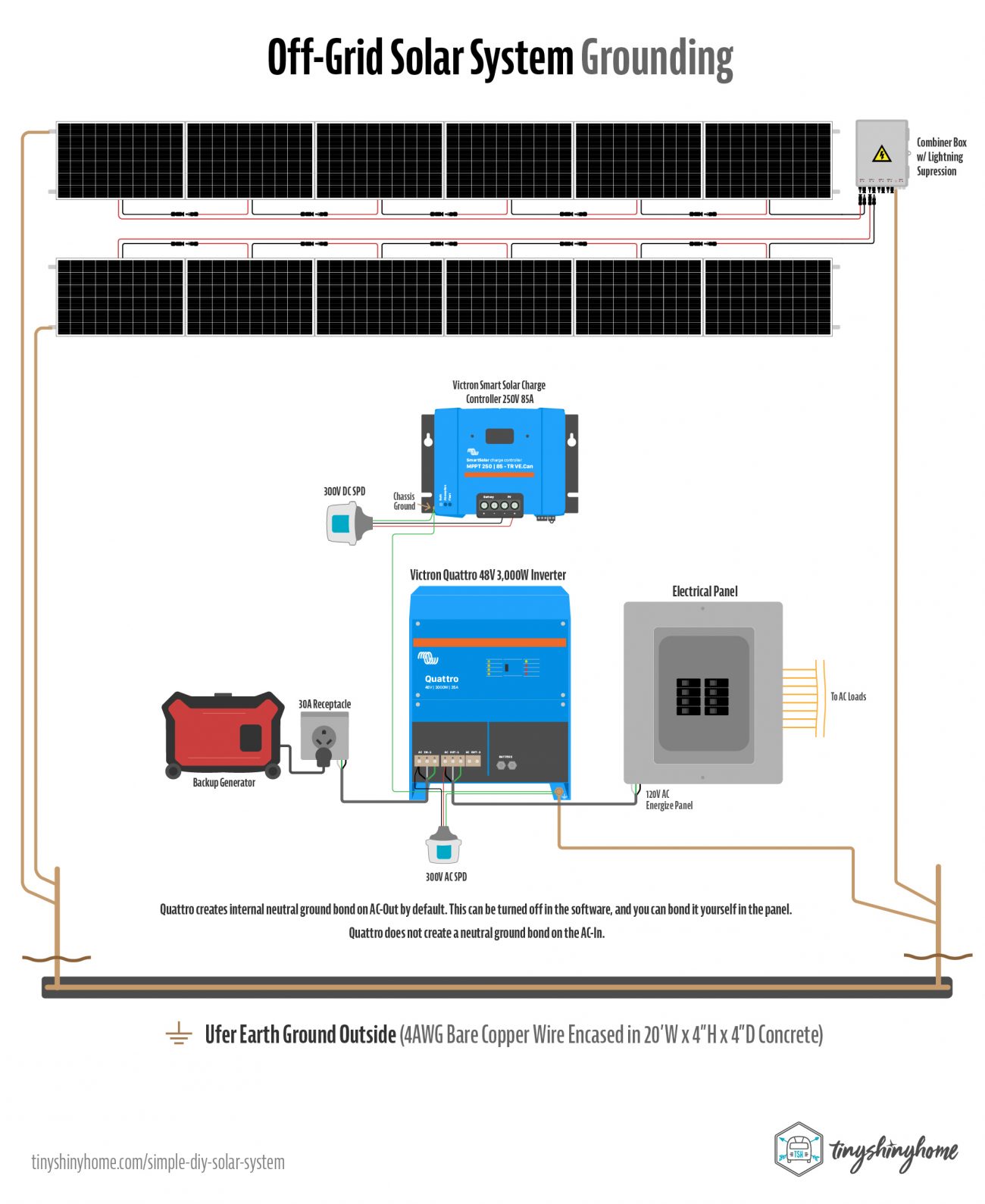
Why did I leave grounding until last? Because I’ve already been bitten once by indirect lighting strikes and poor desert soil conductivity. It was an expensive lesson. Grounding an off-grid system is complicated, but here’s what I’ve learned since then.
First, all your grounds should be connected together if possible. For this system that means:
- Combiner Box
- Each Individual IronRidge Rack Array
- Solar Charge Controller Chassis
- DC SPD Ground
- Quattro AC Out-1 Ground
- Quattro AC In-1 Ground
- Quattro Chassis
- AC SPD Ground
- Since the shipping container building was metal, and lifted on blocks it needed to be grounded as well
Second, desert sand and a single 8’ ground rod won’t cut it. For this install we poured an Ufer ground - 20’w x 4”D x 4"H of concrete encasing a 20' of 4AWG bare copper wire with 8’ ground rods connected on both ends. The block of concrete acts as a better grounding circuit than our native soil.
All the gear inside grounds to the Quattro chassis lug, then a 4awg wire runs to the container and to the Ufer Ground.
All gear outside has it’s own 4AWG bare copper wire running to the Ufer as well.
The goal here with the Midnite Solar SPD’s is that should a lightning strike occur, they will blow and shunt the excess voltage through the ground into the Ufer ground and not damage our gear inside.
Note: For those wondering about neutral-ground bonding, the Quattro does this internally by default for the AC-Out. You can turn the Ground Relay option off via software and do your own bonding in your panel (recommended).
The AC-In does NOT internally bond the ground and neutral.
Booting & Settings
Ok are we finally ready to start this thing up? If you haven’t already, install that T-Class Fuse into its holder and cover it with the plastic cover. Next turn on the 100A Single Pole Toggle going from the solar charge controller to the battery. This will ensure that when it starts up it’ll set itself to the proper voltage.
Do not turn on the breakers in your solar combiner box or the 20A breaker inside yet.
Next we need to startup the SOK battery. For a system this small, we can use the built in automatic pre-charge. Turn on the DC Breaker located on the front of the battery. Then press the RST button with a small item like a pen. This will immediately engage the pre-charge circuit of that battery, which will charge any capacitors in the system. The internal BMS (Battery Management System) will do its checks, you’ll hear a clunk, power will be turned on from the battery, and things will start booting up.
Note that the Cerbo GX firmware will need to be updated to at least 3.0.0~15 in order for the SOK battery to communicate properly. So the next step is to connect the Cerbo to the internet and do the update before anything else.
Once it reboots, you should see all your devices listed when going to the Device List page, including the battery. Using the touch screen (or Remote Console on your phone if you don’t have a touch screen) make a few settings changes:
- Settings > System Setup > DVCC
- Main > On
- Limit Charge Current > On
- Maximum Charge Current > On
- Maximum Charge Current > 90A
- Shared Current Sense > On
- Settings > System Setup > Battery Monitor > Plyontech on Can Bus
- Settings > System Setup > Battery Measurements > Plyontech battery
Current Connected also recommends setting fallback charge settings in both the charge controller and inverter in case connection via the CAN-BUS is lost. You’ll do this via the VictronConnect App on your smartphone, and connecting to each device individually via Bluetooth. These will likely need their own firmware updates so go through that process as well.
- Charge Current for normal use: Up to 63A (Per Battery)
- Charge Current for fast charge: Up to 95A (Per Battery)
- Absorption Voltage: 57.6v recommended; up to 58.4v max
- Absorption Time: 15 Minutes
- Float Voltage: 55.2v
- Charging Target: 100% SOC
- Low Voltage Shutdown: 48v
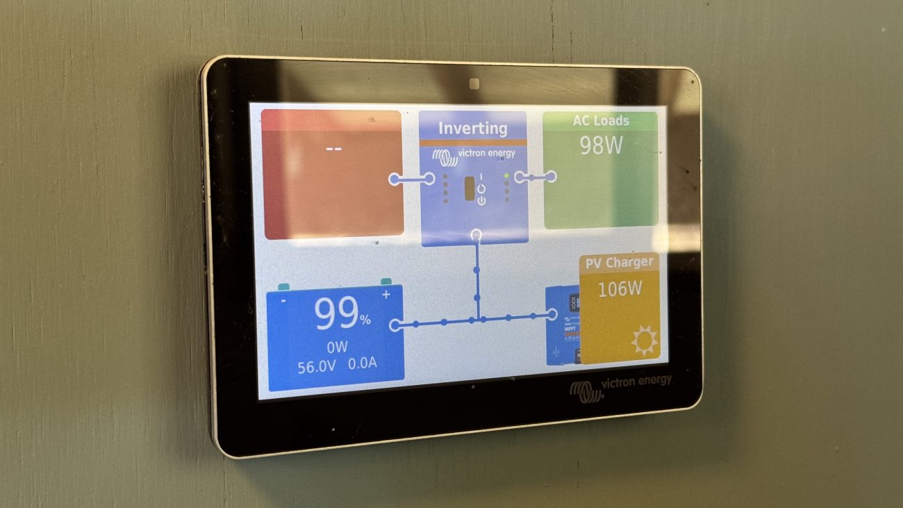
At this point, you should be seeing the battery voltage and percentage on the home screen. Provided it’s got a decent charge, let’s go ahead and turn on the Inverter, and test your 120V power. The screen should change to “inverting” and the AC Midnite SPD should turn one blue light on.
Test that your breaker panel has been energized with 120V, turn on a few circuits, and run some tests.
Now let’s turn that solar power on. Go outside to the combiner box and flip the breaker on the inputs you’re using. Then go inside and turn on the 20amp Breaker. You’ll see both lights turn on in the DC Midnite SPD, and the charge controller will slowly ramp up until the full amount of power is coming in. Now you’re charging your battery!
Finally, if you installed a generator input, use an MK3-USB Cable to connect your computer to the Quattro and change the input current limit appropriately. Our Harbor Freight 3500 runs comfortably at 20A. Then turn it on and plug it in. You may need to change which input is listed as what in the Cerbo (i.e. set AC In-1 to be “generator”) so that it shows the right name and amount on the homepage.
Turn on your generator, and watch the Quattro turn into a charger, using that power to fill the batteries. The second light from the AC Midnite SPD should turn on as well.
If you’ve sized the system right, you shouldn’t need to use this very often at all - but it’s a nice backup.
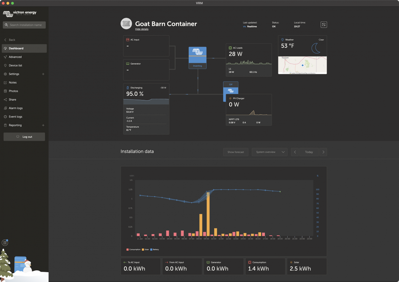
Want to see all this glorious, nerdy data remotely? Connect the Cerbo GX to the internet via WiFi or Ethernet, go to vrm.victronenergy.com, create an account and create a new install using the ID from the Cerbo.
Then you can use the website or apps on your phone or computer to monitor the system from anywhere in the world.
What to Expect
Ok, let’s set a few expectations. First of all, your battery cells need to balance. And this will take a long time, especially if you only have solar to charge them with. Count on a full two weeks of High Voltage Alarms & Warnings in the Cerbo sent by the battery BMS. Yes it really can take that long. I’ve installed several systems now, and they all seem to require that much time.
The nice thing about the SOK batteries is that the BMS is built in, and it should just be talking to the Cerbo without needing to change much.
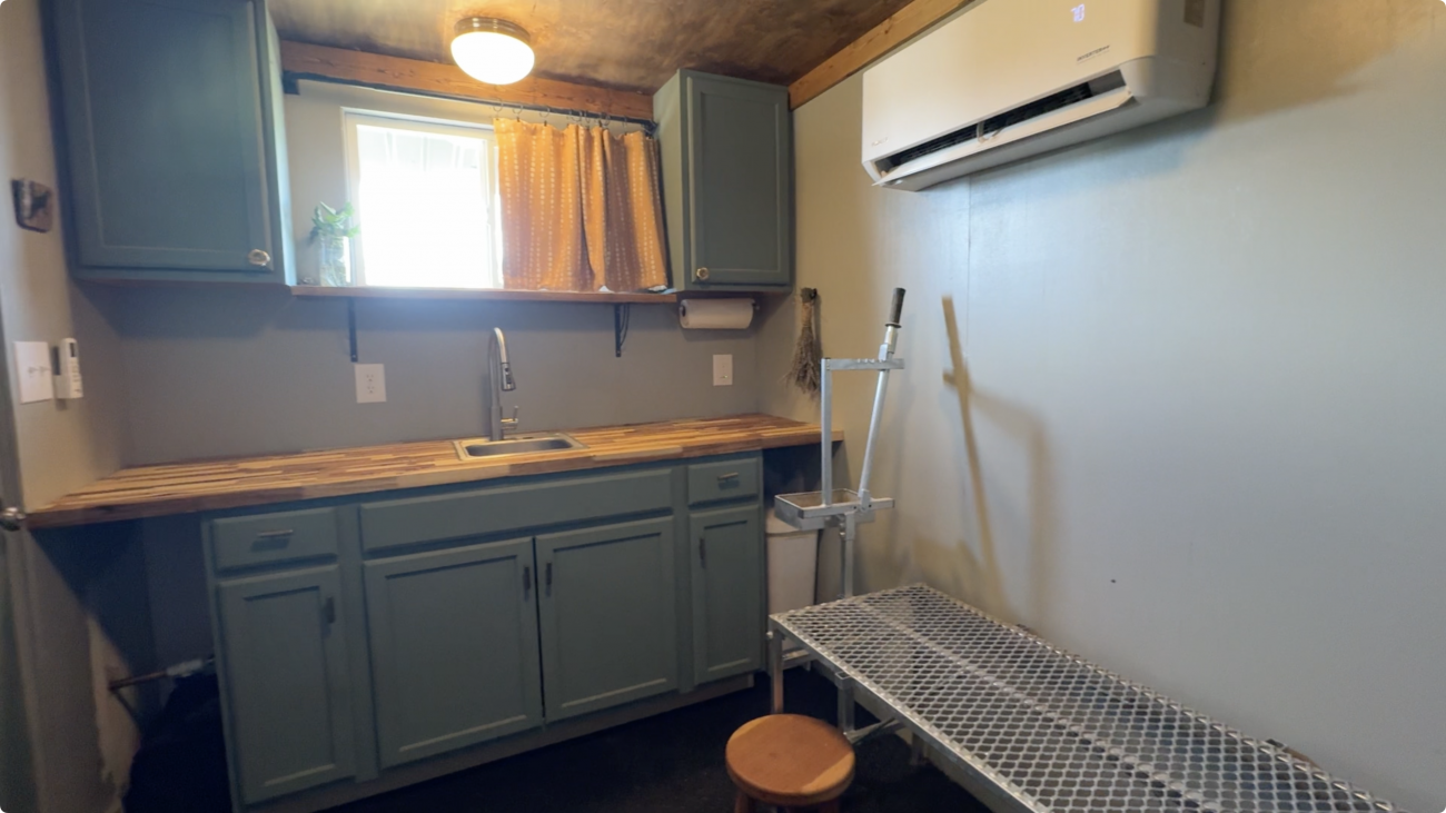
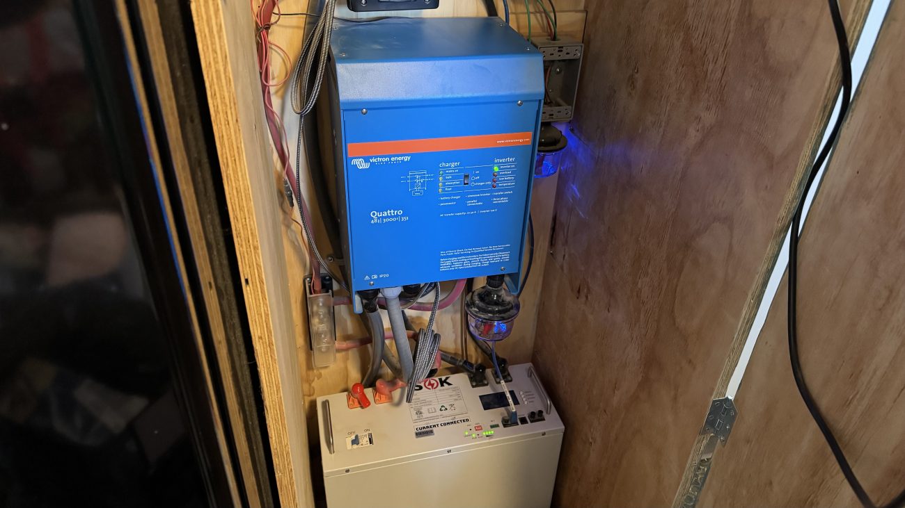
We’ve been using this system for about 6 months, and on average produce 6kWh a day, with most of that coming from the mini-split air conditioner. The battery drops to 30%-50% overnight, and just a few hours in the morning charges it back up. It’s handled an unseasonably hot summer and fall like a champ, and so far we're using even less power using the heating function to keep it warm this winter.
Looking to the future, if we find the battery storage to be too small, adding a second 5kWh battery to the system is very easy.
Cost Breakdown
How much did it cost? As usual we'll break it down for you in excruciating detail :)
Note: Some of these are affiliate links, use if you like. DO NOT buy Victron gear from Amazon (we learned this the hard way). Our Victron and IronRidge links will take you to our supplier (NAZ Solar Electric), but make sure you get yours from a local authorized dealer that can actually support you long term.
Battery
The first piece is the battery, including cables, lugs, and protection.
Item | Cost |
|---|---|
| $1,575.75 | |
| $9.99 | |
| $47.00 | |
| $39.00 | |
| $51.00 | |
| $73.00 | |
$14.91 | |
Total | $1,810.65 |
Solar Charge Controller
Next we need the charge controller, breakers, lugs, and SPD lightning protection.
Item | Cost |
|---|---|
| $504.69 | |
| $67.00 | |
| $13.00 | |
| $13.00 | |
| $13.00 | |
| $10.00 | |
$30.00 | |
$42.00 | |
$13.60 | |
$100.34 | |
Total | $806.63 |
Inverter
Use the inverter to generate clean 120V power for your appliances.
Item | Cost |
|---|---|
| $1,576.56 | |
| $100.34 | |
| $31.44 | |
| $90.00 | |
Total | $1,807.33 |
Cerbo GX
The brain that all your Victron gear will connect to so all pieces work in sync.
Item | Cost |
|---|---|
| $266.40 | |
| $202.35 | |
| $15.30 | |
Total | $484.05 |
Solar Panels
Build your own array and make your own wires.
Item | Cost |
|---|---|
| $360.00 | |
| $202.35 | |
| $14.00 | |
| $82.00 | |
Total | $658.35 |
Solar Racking Mount
Roof Mount IronRidge Racking System.
Item | Cost |
|---|---|
| $766.00 | |
| $29.96 | |
| $86.80 | |
IronRidge UFO Stopper Sleeve x 8 (replaced with EFO's) | $4.16 |
| $11.30 | |
| $95.40 | |
| $65.62 | |
| $12.19 | |
| $189.00 | |
Total | $1,260.43 |
Grounding
Make sure your lighting surge protection actually has a way to shunt spikes to an Ufer ground.
Item | Cost |
|---|---|
| $215.00 | |
| $87.00 | |
| $9.80 | |
60lb Concrete x 8 (4"x4"x20' block) | $122.40 |
Total | $434.20 |
Tools & Connectors
We couldn't cover the install without mentioning the tools and connecters we needed to finish the job.
Most of these are pretty basic, but if you've never built your own cable before by crimping and heat shrinking a lug on, you may not have everything laying around.
Item | Cost |
|---|---|
| $21.10 | |
| $18.95 | |
130 PC. Dual Wall Adhesive Marine Heat Shrink Kit - 3:1 Shrink Ratio - Black and Red | $9.97 |
| $12.49 | |
| $12.82 | |
| $54.99 | |
$23.99 | |
| $8.99 | |
| $179.00 | |
Total | $342.30 |
Totaling it Up - How Much Did it Cost?
I know, I know - you're all like "Just tell me the total already!" Fair enough :) Here's the breakdown:
Item | Cost |
|---|---|
| Battery Bank | $1,810.65 |
| Solar Charge Controller | $806.63 |
| Inverter | $1,807.33 |
| Cerbo GX | $484.05 |
| Solar Panels | $658.35 |
| Solar Racking | $1,260.43 |
| Grounding | $434.20 |
Total | $7,261.64 |
Wrapping Up
Whew! I’m not sure how I keep talking myself into writing these massively detailed posts, but here we are again.
I hope our installation breakdown and wire guide give you a better understanding of how to build your own simple off-grid solar power system, and do it in a way that is safe, stable, and cost effective.
If you found this interesting I have to let you know that we’re just getting started here on our off-grid homestead. Besides building all sorts of unique, sustainable structures we’ll be setting up rainwater catchment, and even creating other smaller independent solar systems for various uses. So much going on, and we’d love to share it with you! Make sure you’re subscribed so you don’t miss our next project.
Until next time!
Download Our Solar Wiring Diagram
Get up close and personal with this super detailed, impeccably illustrated hi-res PDF of our full off-grid power setup with a schematic representation of how everything in our 3kW, 5kWH, 120V off-grid battery and solar system connects together. Includes bonus individual component wiring configs, too!
Apparel
Grab a fun, comfy t-shirt & help support our family.
comments powered by Disqus


