Solar Powered Pump House - How We Get Pressurized Water on Our Remote Homestead
Today we’re going to take you through the evolution of our solar powered water pump house design that has provided us with pressurized water on our remote property - allowing us to mix soil to build earthbag structures, wash dishes in our RV, drip irrigate 70+ trees, shower outside, and even run a washing machine - all without drilling a well or having power brought in.
We’re on our 4th pump house now. What started out as a very simple idea has morphed over the years into a much more sophisticated setup so today we’re going to walk you through each version - what we learned, what worked, and what didn’t - so you can decide which version is going to make the most sense for you as you build your own solar powered pump house.
Disclaimer: Before we get started, I want to make sure you know I’m not an electrician or plumber, nor am I sponsored by any of the companies we’ll talk about. We chose our equipment based on our needs, and we’re just sharing our experience. We hope you find it helpful.
FYI You can always read through this article, and learn everything you need to know - but if you’d like to say thanks or want to download high-res diagrams of these plans you can can buy the guide here:
Build Your Own Off-Grid Pressurized Water System!
Want to save this article and video for later? Our detailed walk-through & planning guide will help you design & build 3 different solar powered pressurized water systems for remote off-grid applications.
Article Overview
- Original Pump House Fail & Big Idea
- Pump House Enclosure
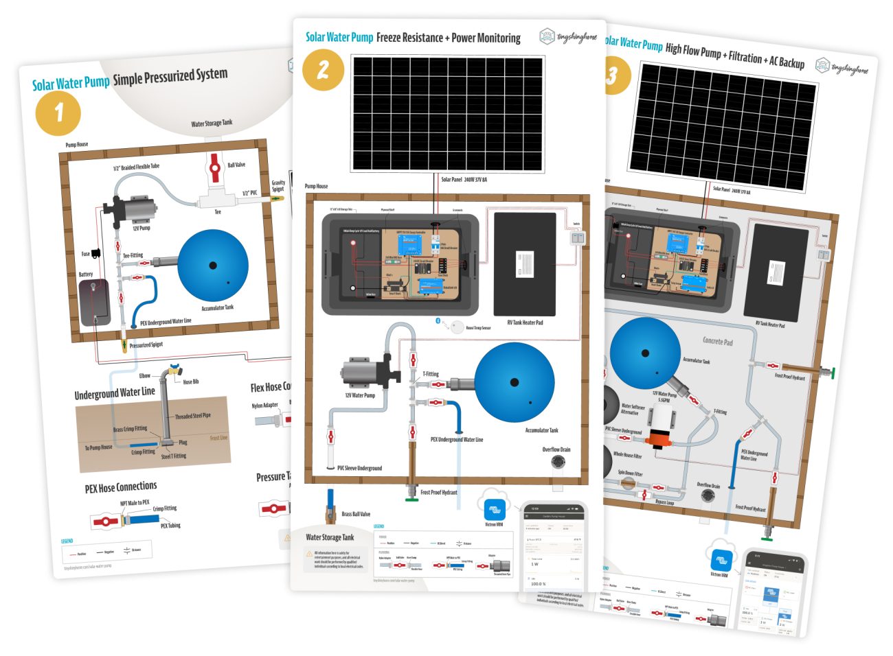
- Option 1: Simple Pressurized System
- Option 2: Freeze Resistance + Power Monitoring
- Option 3: High End Permanent Installation
- Shopping List
- Wrap Up
Our Original Pump House Failed, But This Big Idea Fixed It
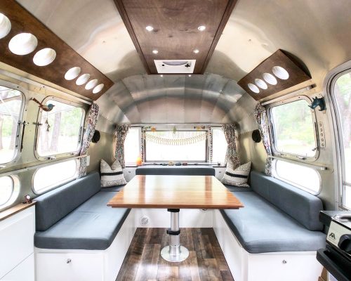
We stumbled on this idea out of necessity: after pulling our 1972 vintage Airstream onto our raw land in SE Arizona we quickly realized water was our first priority.
Here, drilling a well is cost prohibitive - to the tune of $70,000 or more. And because of unregulated big agriculture and dairy farms in the area, the water tables are dropping quickly. So we didn’t feel like a well was a good investment. Long term we’re focused on rainwater catchment, but at the beginning we had no roofs to catch water on - so we had to get creative.
First, we bought a 2,600 gallon water storage tank that was permanently set on the property. We’d throw a 330 gallon IBC Tote in the back of our truck, drive to a nearby wellshare, fill it up, and transfer the water into the big tank ourselves with a generator and transfer pump.
Then we used the transfer pump to put 40 gallons into our fresh tank in the Airstream each morning. The onboard pump in the RV would then make that water come out of our faucets and showers. As you can imagine that got old really fast, so we started dreaming up alternatives.
Eventually we would build a huge off-grid solar system on the property, but at the time all we had was the 2000w inverter in our Airstream.
So we built out an entire version of this pump house with a power hungry pump and hardline PVC piping. And it didn’t work. Since our batteries were 12V the startup of even small shallow well pump would cause voltage drop and trip the inverter in our Airstream. Plus when it did manage to pressurize, all the fittings kept leaking.
It was at this point that we realized we needed to start over. How could we build an independently powered, pressurized pump house without investing in a much larger power system or generator?
Turns out the answer was already in our RV. After some tests we realized the 12V pump in our RV was powerful enough to pressurize the amount of water we needed, and could be run on a battery and solar panel. Adding a pressure tank made the output more consistent and helped put less wear on the pump motor. Plus since the RV pump already had a pressure switch and check valve built-in plumbing was easier.
Over the years we’ve taken this simple idea and iterated on it, adding additional freeze protection, smarter power monitoring and notifications, even filtration systems.
But let’s not get ahead of ourselves. First, we need to build the enclosure that we'll install everything in.
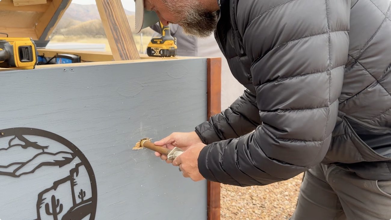
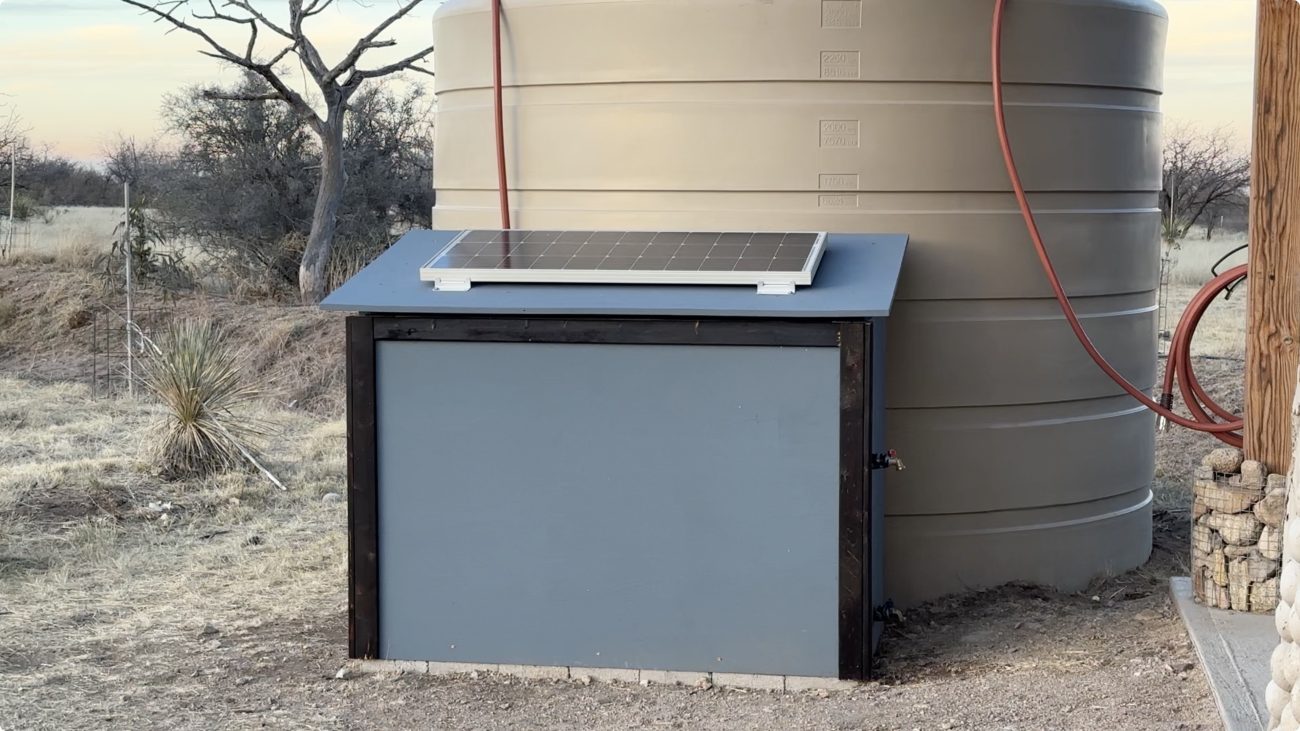
Building the Pump House Enclosure
The pump, power system, and plumbing need to be in something so they’re protected from the elements. We’ve tried this a few different ways, and we just keep coming back to 2x4’s and plywood.
The size will really depend on what all you’re putting inside, but 4'x6' is a great place to start.
If this is just a temporary pump house then you could set down some concrete pavers and build a 2x4 framed floor with insulation in it.
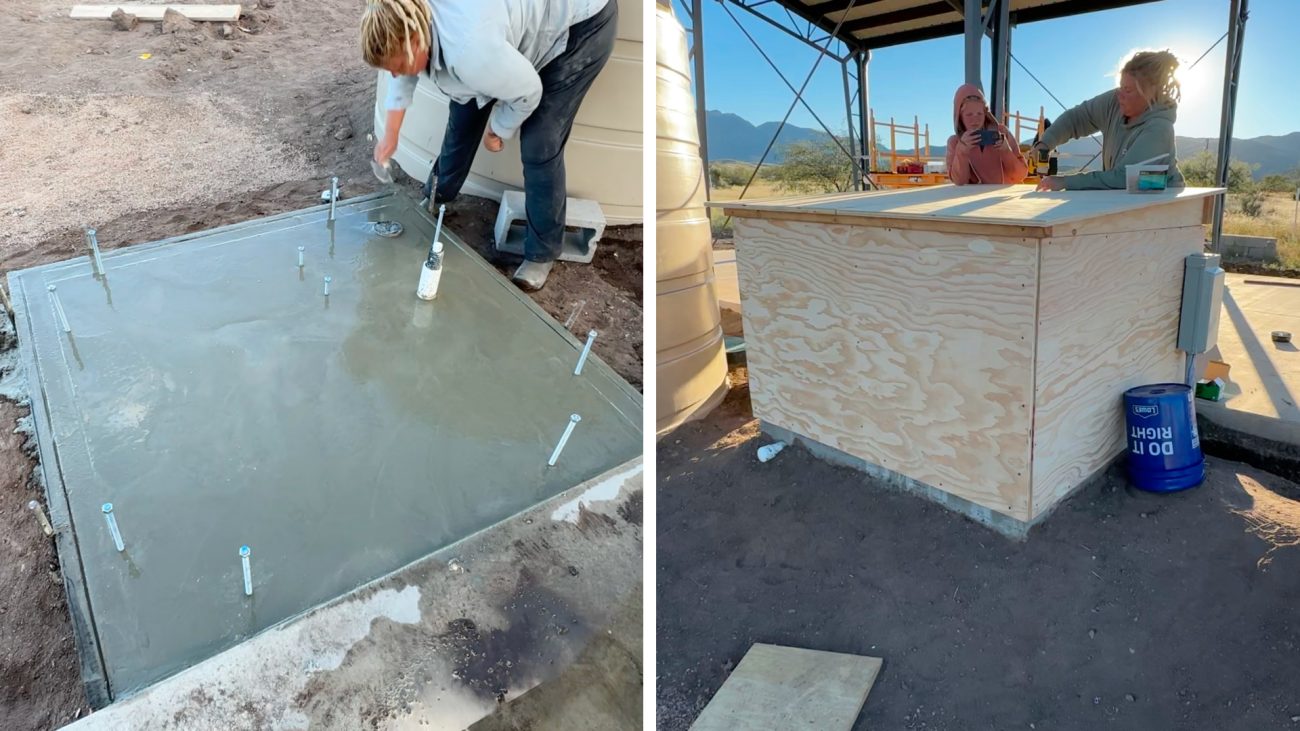
For a more permanent pump house you can pour a small concrete pad. Put some bolts in to attach the frame to, put an overflow drain in for when it leaks, and stub up some PVC pipes so you can bring the water from the tank in and send it out to remote spigots.
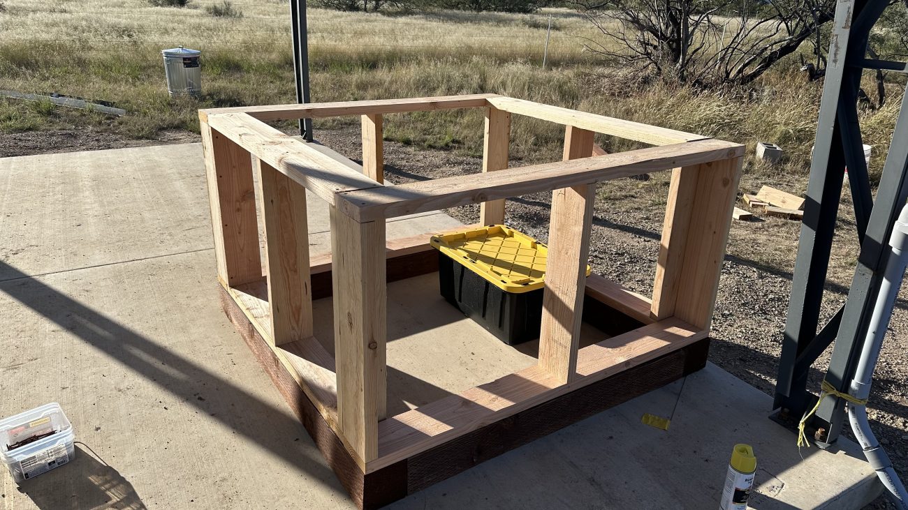
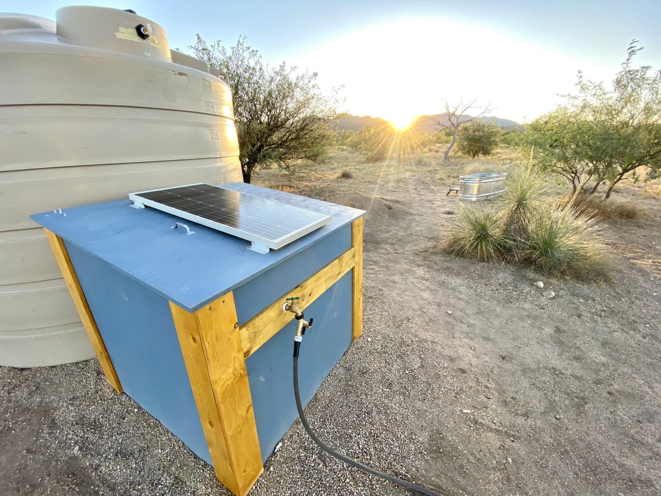
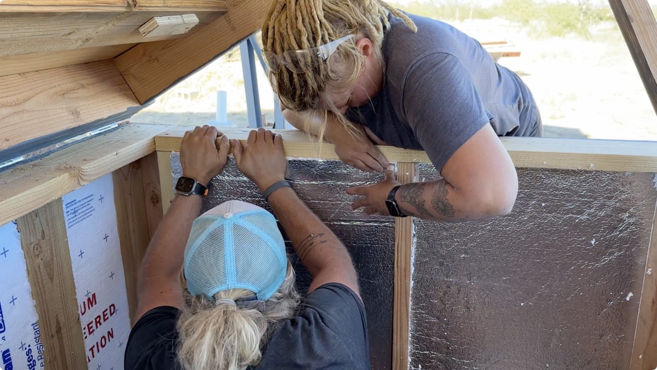
Build your walls up about 3’, put plywood on the outside, fill the cavities with insulation, and then build slanted shed style roof with hinges so you can access the inside. Bonus points if you slant that roof South to put your solar panel on.
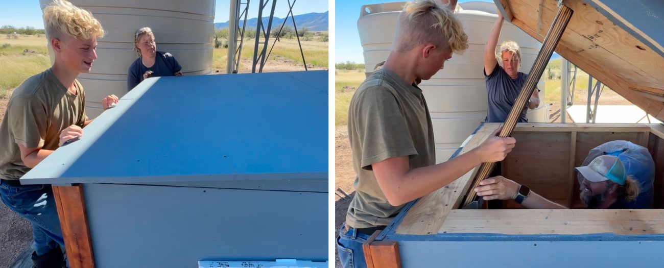
We usually build these half height boxes because you use half the material, and don’t have to buy expensive bits like doors or windows. Plus there would just be a lot of wasted space for such a small pump system.
But, they can be hard to work on since you’re reaching down into a cavity. So if you want to just build something walking height with a door you go for it.
If you can place the box right next to your water tank, cut a hole in the back and slide the pipe coming from the tank through, wrapping the exposed area with insulation to keep from freezing.
If you’re in a colder climate, and want better protection - take your pipe directly down in to the ground and then up through the bottom of the box.
Hopefully we’ve given you some good ideas, but the box can really be whatever you want. The main point of this guide is to teach you how to build the power and plumbing system. So let’s start with the easiest version of the solar water pump system and work our way up.
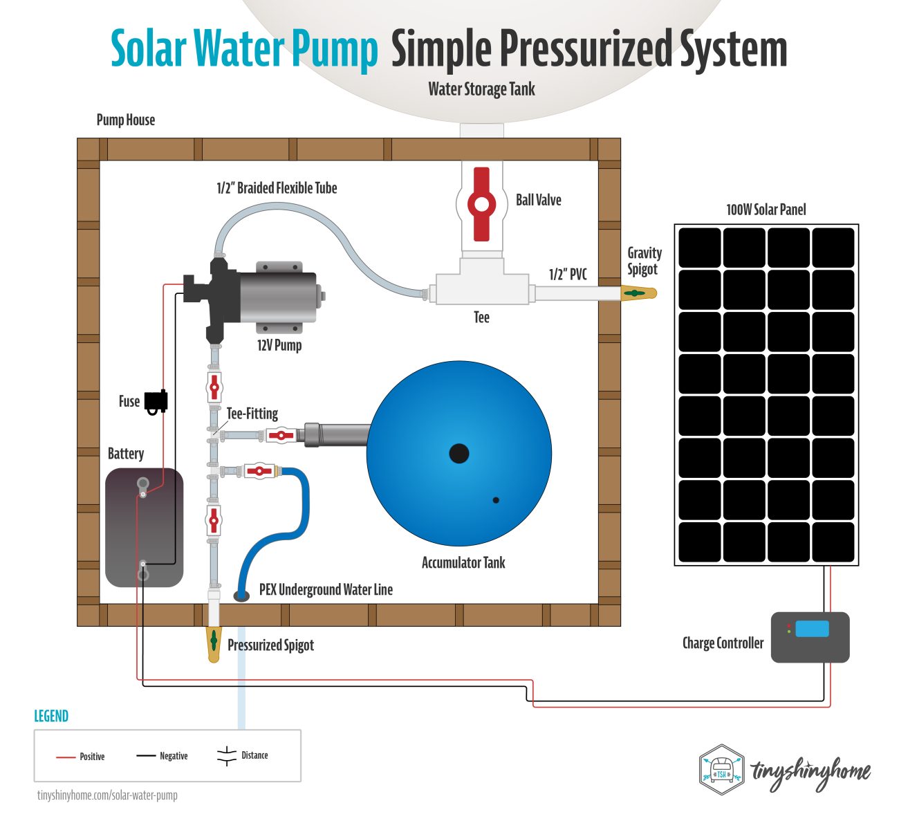
Solar Pump House Option 1: Simple Pressurized System
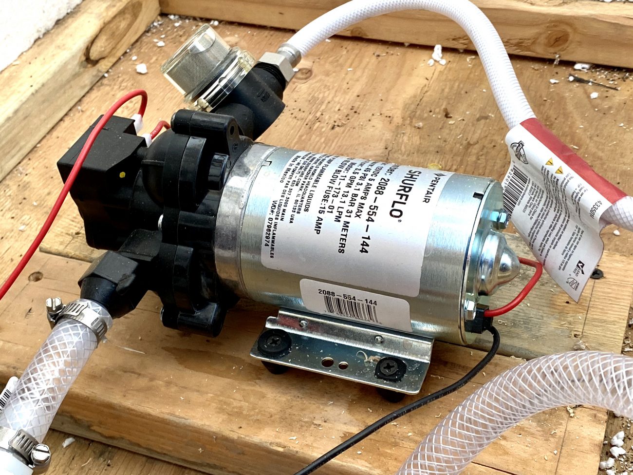
The simplest version of this pump house uses a Shurflo 3.5gpm 12V Pump - the exact same pump we've had in our Airstream since 2017. It’s by far the most rock solid pump we’ve used on any of these builds. They just don’t quit!
Remember, power was our biggest limiting factor for our original pump house fail. But with a small 12V pump, this becomes much more manageable.
Electrical
To keep it simple we recommend something like the Renogy 100 Watt 12V Monocrystalline Solar Starter Kit for about $120. It includes the panel, a solar charge controller, panel mounts, and all the cables in the same box. Easy!
Grab a Deep Cycle 100AH 12V Marine Battery. You might be wondering why not a fancier Lithium Iron Phosphate battery? Well, flooded lead acid batteries are cheap, simple, and work in pretty much any temperature environment. LifeP04’s are a little more fragile, need a BMS and heater to keep working during the winter.
Time to start wiring it up.
The first connections in line will be the positive PV (Photovoltaic) cable from the solar panel to the positive PV input on the charge controller, then the negative PV cable to the negative PV input. But I would wait to connect these until the very end. This is so you don’t have power flowing from the panel to the charge controller while you’re wiring everything else up.
Out of the charge controller run the positive battery wire to the positive lug on the battery and the negative to the negative lug. Renogy’s cables come with ring terminals attached, but for the rest of the connections you’ll need to know how to make your own cables.
If you haven’t made your own connections before, it’s pretty simple. You’ll want some wire strippers, a set of terminal rings, and crimper.
The terminal rings have two measurements - the first is the wire size it will accept, and the second is the size of the hole in the ring itself.
For this setup you’ll be using 12AWG black and red wire so you’ll want a box of 10-12AWG with a 3/8” ring which is big enough to fit on the post of the battery. These are usually yellow.
To make the connection strip the coating back so the copper is visible - just enough so that when inserted you can’t touch the bare wire inside the insulated area. Then using the correct color on your crimp tool make a nice tight crimp. Yank on it to make sure it won’t come loose.
Then make up positive and negative wires from the battery to the RV pump.
Since we’re not using a load center in this setup you will want to wire in an inline fuse holder and add a 15A blade fuse on the positive wire from the pump to the battery. To keep everything isolated while making these wires up leave the fuse out until you’re ready to start pumping water.
Plumbing
Speaking of water, let’s look at the plumbing side of this install.
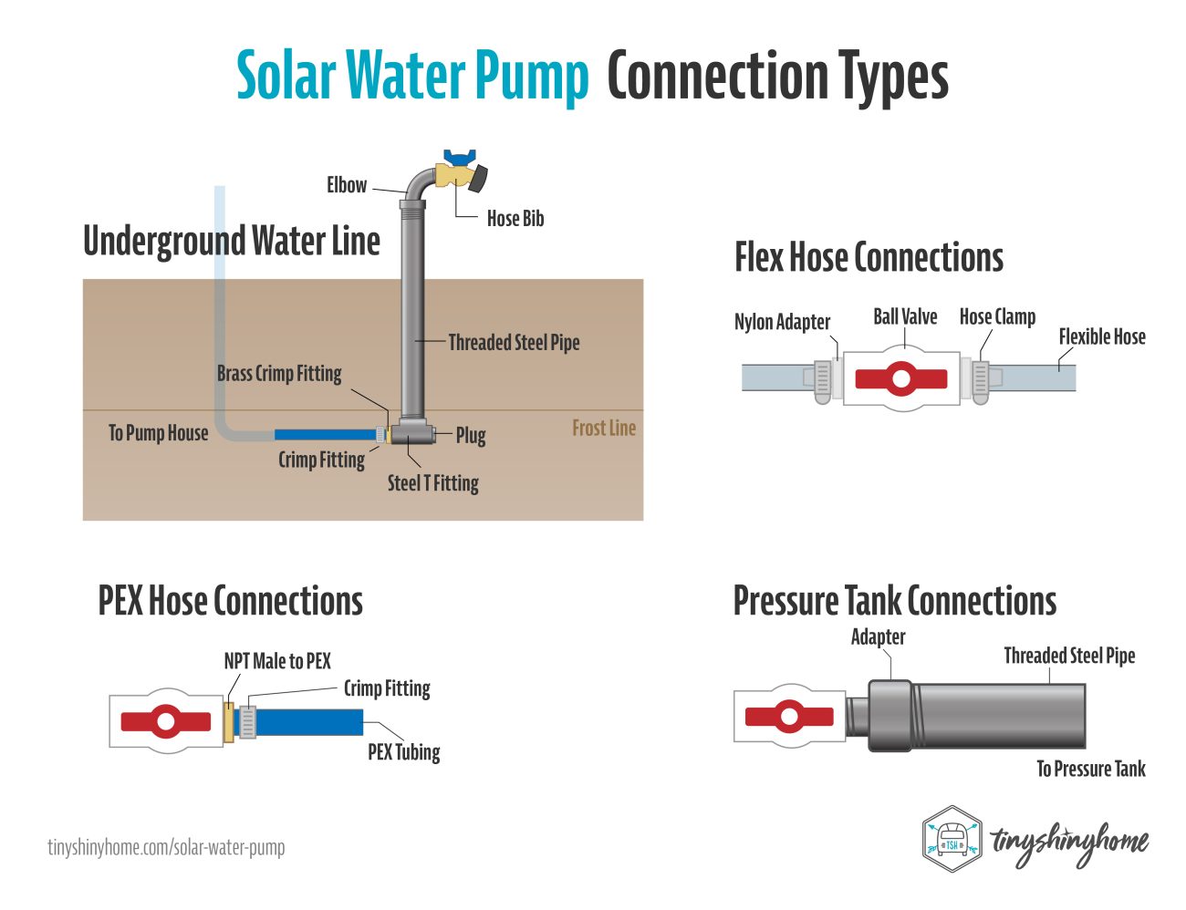
By using a smaller 12V RV pump, we can use 1/2” braided flexible tubing that attaches with hose barbs and hose clamps. There are a few benefits to this.
- It means physically connecting everything in a small space gets a lot more flexible.
- The clamps allow you to take apart, change things, and repurpose without breaking anything like gluing PVC or crimping PEX would.
- The nylon fittings and tubing can slightly expand and contract making it more resilient during freezing conditions
The pump itself also has several benefits:
- The check valve and pressure switch are built in, simplifying plumbing
- It’s small and easy to mount in tiny spaces
- Uses very little power, and combined with an accumulator tank will give you plenty of pressure
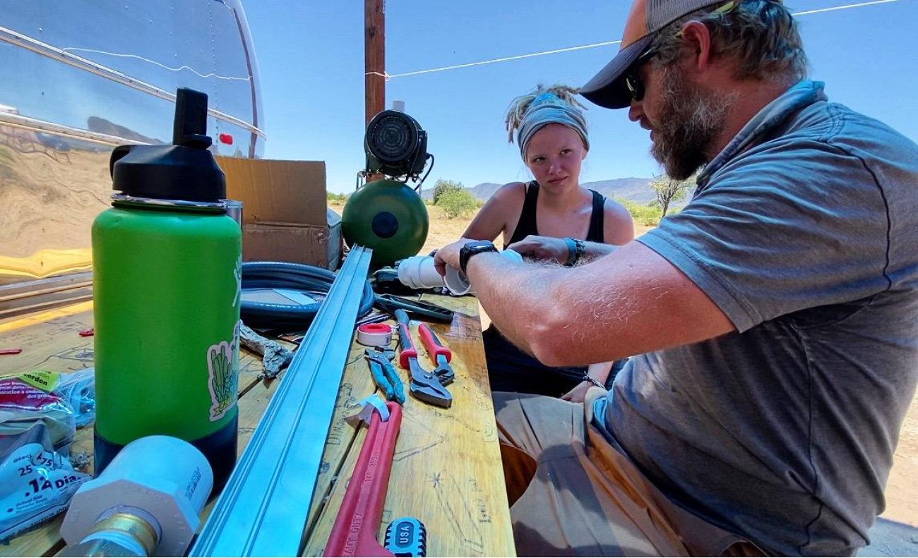
I should say, each of these plumbing diagrams are just suggestions. My goal with this is to show you the basics of how to setup different connections - and then you can decide which ones you want depending on your specific needs.
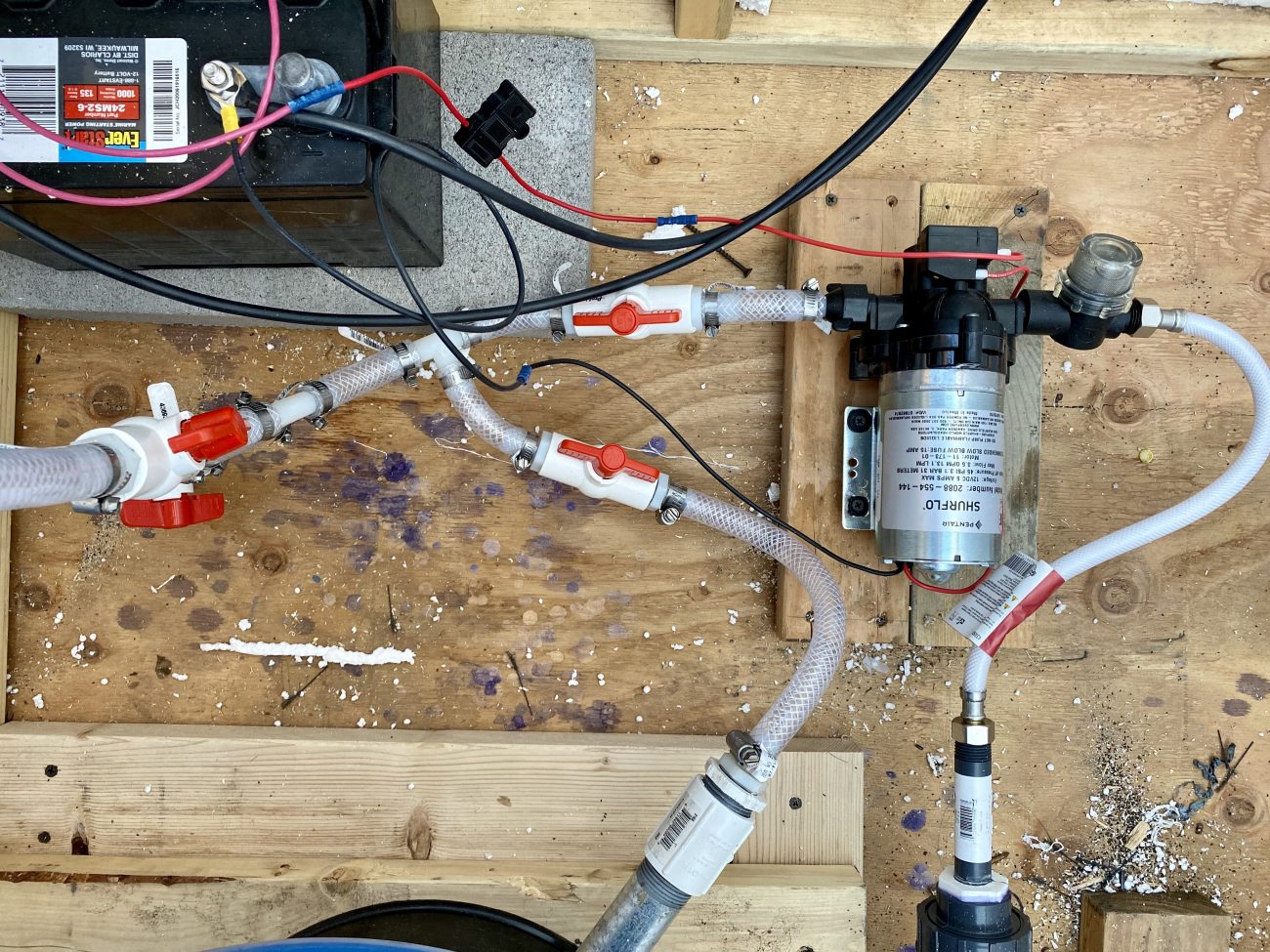
Now, as you start plumbing everything remember that ball valves are your friend. They are a great way to isolate each individual piece of your system during maintenance or troubleshooting. So starting with your water tank, you want a shutoff right at the source. This will depend on what kind of fitting your tank has - our first one had a 3” threaded port so we installed this huge 3” ball valve. It’s kind of overkill, but it works.
Most tanks will have a 2" threaded port so install a bushing reducer and a heavy duty ball valve. From there you’ll just need to head to the hardware store and grab the PVC plumbing you need to get to a tee fitting that steps down to a 1/2” female threaded adapter.
Our first pump house had what we called a “gravity spigot” - a low point drain that would let water come out without the pump if needed. That’s where the first side of the tee goes. In reality we rarely used this, but it was a good way to drain the system if we were worried about freezing.
On the other side of the tee is where we switch over to the flexible tubing and hose barbs.
You’ll be using a lot of 1/2” hose barb x 1/2” Male NPT fittings. We recommend good quality plumbers tape wrapped several times clockwise, and some pipe dope when you thread your connections in. Tighten by hand and then using a wrench add a few more half turns. Don’t over tighten.
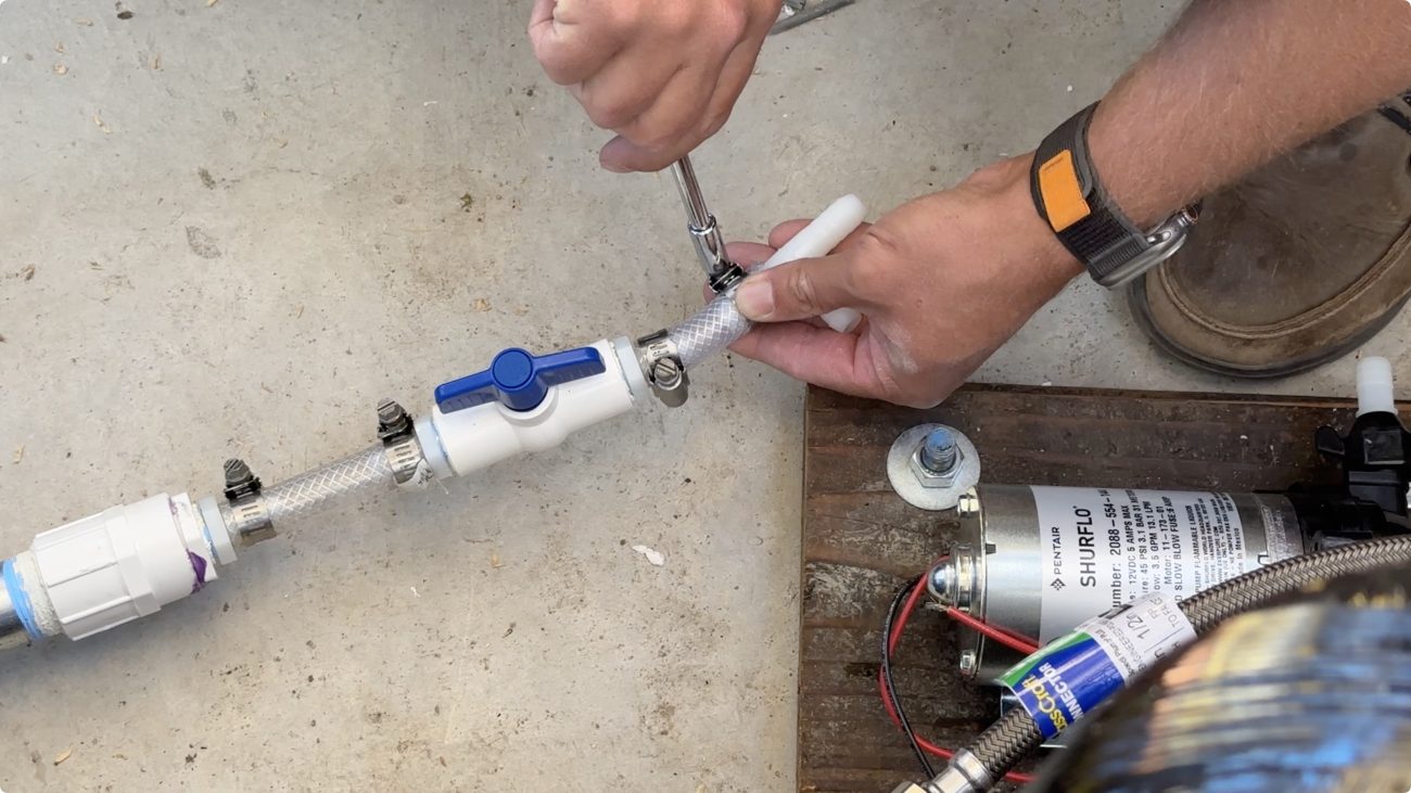
On the pump side you’ll need to buy a few additional items. Get the strainer filter and screw that on the input side of the pump. I’ve never needed any tape or dope on this, just make sure you don’t cross thread. Then buy a 1/2" FPT X 1/2" Barb Straight Swivel and attach it to the filter.
Cut your flexible tube to the right length and slide on a 5/16” Miniature Hose Clamp on each end. Push the tube onto the barb all the way, then slide the clamp down near the end and tighten with a socket. I always try to turn these where I can easily access the head later for tightening or disassembly.
Now you have water coming into the pump. Where does it go from there?
For the purpose of this example, we’ll send the water to a pressure tank, to an underground line, and to a spigot right on the outside of the pump house.
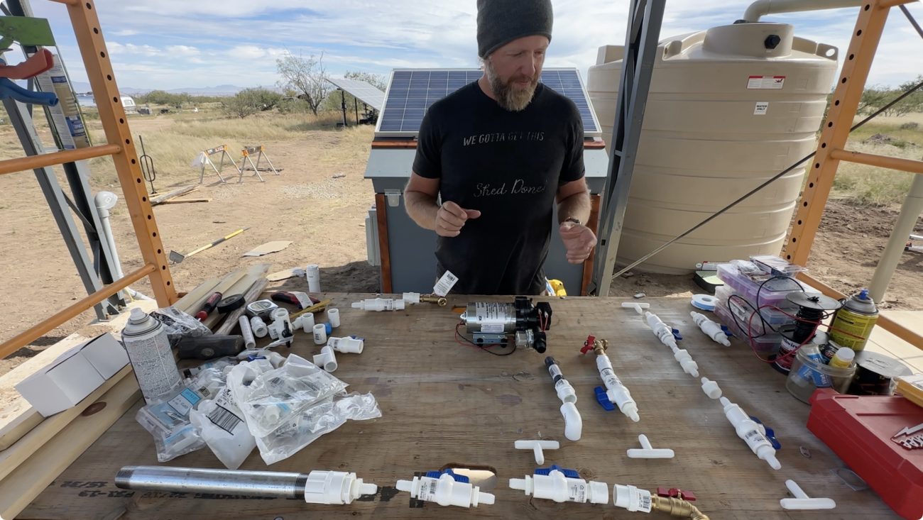
I recommend buying all your pieces and laying things out on the table before you start assembling. Even better, go ahead and thread all your hose barbs into your ball valves so that connecting the flexible tubing goes quickly.
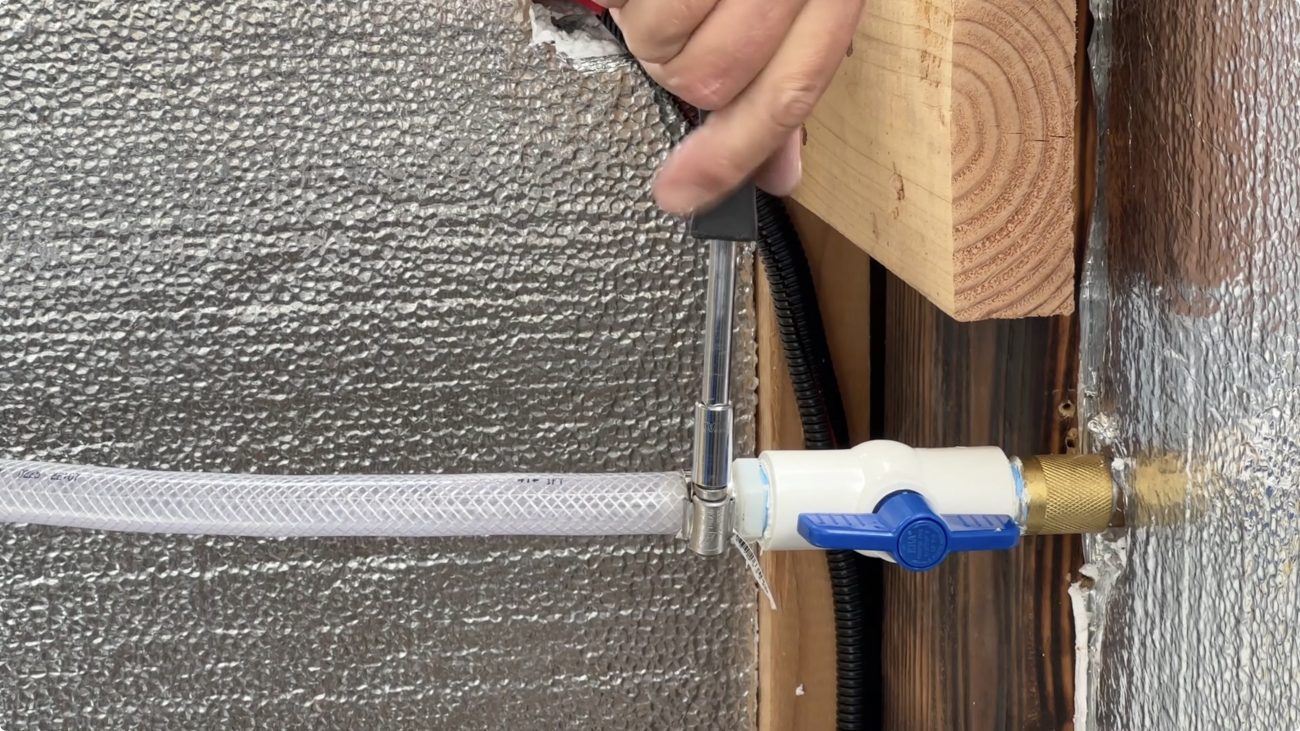
On the output of the pump, add another 1/2" FPT X 1/2" Barb Straight Swivel and connect to your first ball valve. This way you can stop the pressurized water coming out of the pump in an emergency.
The 1/2” ball valves have Female threaded connections so you’re just adding the male threaded hose barbs to each side, and connecting them together with the flexible tubing and clamps like before.
To have different or separate connections come off this line we’ll introduce 1/2” nylon barb tees with the same idea. Slide a clamp on, push the hose onto the end of the barb, then tighten the clamp.
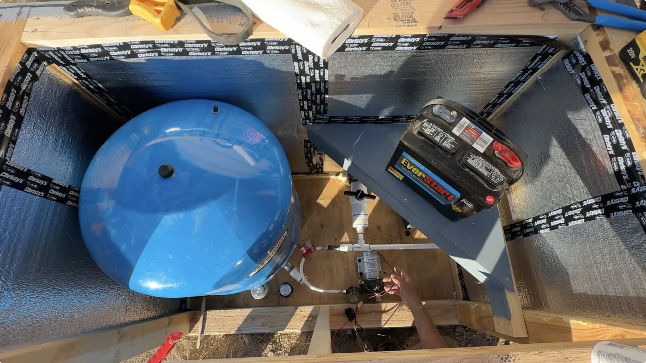
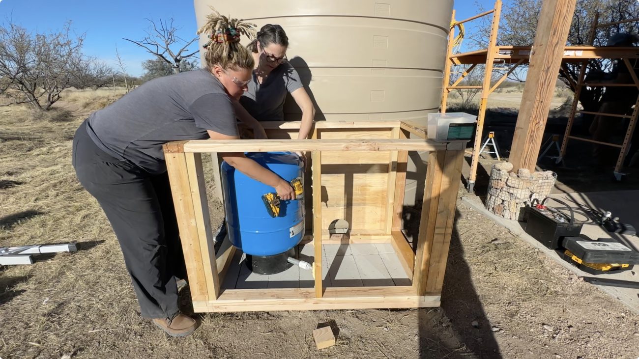
The first branch should go to your accumulator or pressure tank. RV’s use tiny ones, but for a setup like this we like to go with at least a 20 gallon. This doesn’t mean you will store a full 20 gallons of pressurized water, but count on at least half that. We’ll get into how to set your pressure tank later.
For now you’re going to need to transition from a 1” steel male NPT pipe to a 1/2 hose barb. This is always the connection we have the most trouble with. Going from metal to nylon can have a tendency to leak. Our most successful version of this used a reducer to go from 1” to 1/2” Male NPT, then connecting the ball valve straight to that.
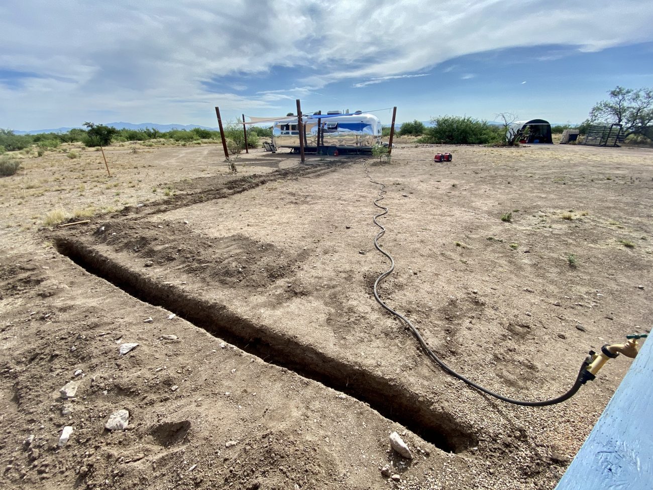
Use your second tee to run an underground PEX line if you need one. Our pump house needed to send pressurized water to our Airstream over 100' away so we converted from the ball valve to a 1/2" Male NPT to PEX Adapter, and ran that through the floor. Note, you’ll need 1/2" PEX crimp rings and a clamp cinch tool if you want to do this.
On the other end we built our own water spigot with a steel tee fitting, plug, threaded pipe, elbow, and hose bib. All below the frost line, of course. If you need more freeze protection look into a frost proof yard hydrant.
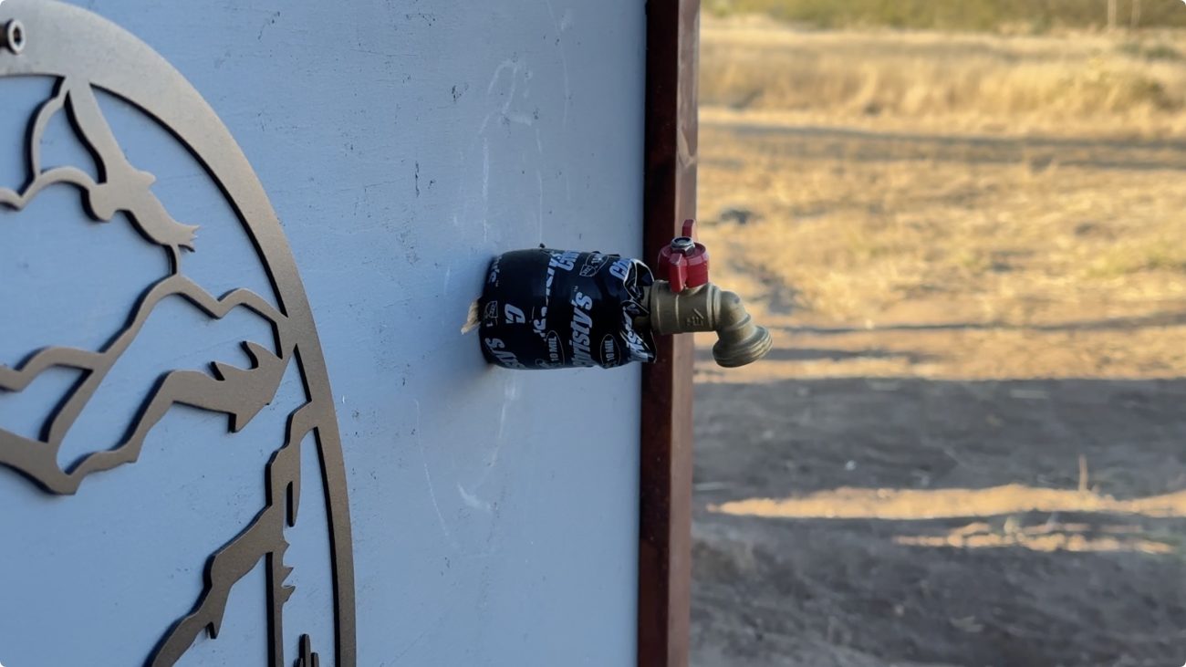
Finally, off the last end of the tee we converted to PVC with a 1/2” Male Adapter and added a simple spigot by drilling a hole through the wall of the pump house and using some plumbing strap to hold the PVC to a stud.
Sometimes we drill the hole a little bigger and wrap the pipe at the end in insulation to help during the winter. This is very minimal freeze protection, though. In the next versions of the pump house we’ll look at some ways to protect against this more.
Now it’s time to start testing! Close all your ball valves, then open the ball valve from the tank to your pump, and put the fuse in. The pump should turn on, start pulling water and turn off almost immediately since it will fill the line quickly and the pressure switch will tell it to stop.
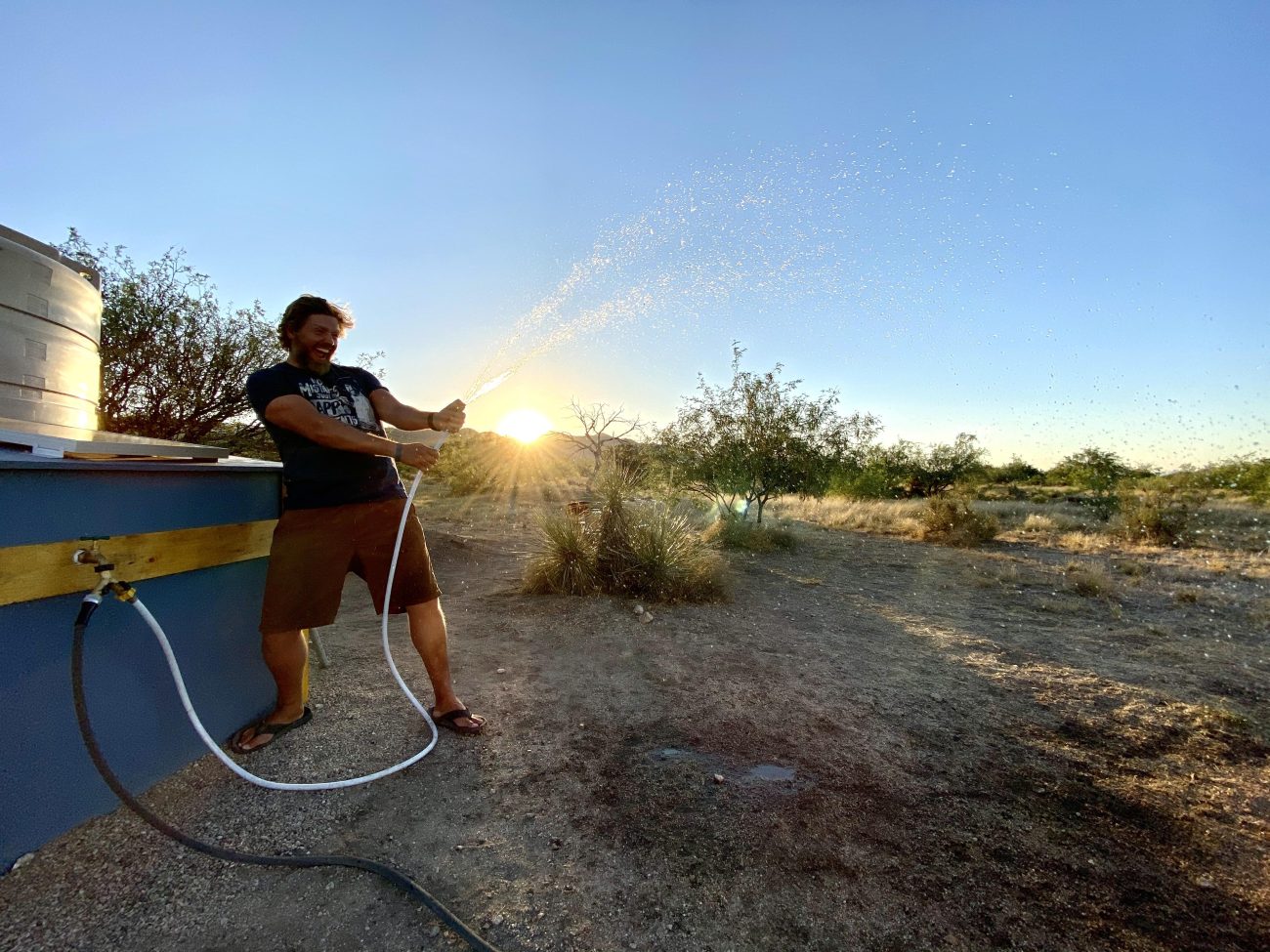
Then systemically open each ball valve and look for leaks. Leave the pressure tank for last so you don’t waste water. Open up your spigots and make sure pressurized water is coming out!
Hose clamp leaks are easy, just tighten them up a bit. Threaded leaks are harder, and sometimes can be fixed by undoing the nearby clamp and tightening a half turn. If this doesn’t fix it then your tape and dope job wasn’t good enough, and you’ll have to re-do it. Finding the right amount of tape, dope, and tightening can be tricky.
Don’t get too discouraged if you have a couple of leaks. The beauty of this system is that you can take almost all of it apart without breaking anything.
Now we need to set your pressure tank. Use a bicycle pump or any air pump that shows the pressure reading, and let the air out until you’re at 25 PSI. This is because it needs to be 2PSI lower than when the pump turns kicks on. If you keep it at the 45PSI it ships with, it’ll hit that full air bladder and just stop, not filling it up.
If you get a different pump you’ll need to find the specs and adjust appropriately. When set correctly the Shurflo 3.5 GPM pump will take about 10 minutes to fill the 10 gallon availability of a 20 gallon pressure tank - so be patient.
If you’re fully pressurized and leak-less go back and make those solar panel connections to the charge controller and set it to “Flooded.” Close your lid, and let the sun fill your battery. This system is oversized so as long as you’re using the pump normally (i.e. not all day), have a decent amount of sunlight, and the panel is tilted towards the sun you won’t run out of power.
Congratulations! You’ve got your very own solar powered pressurized water pump. Now maybe you have questions.
- What if it gets really cold here, and I want more assurances that this won’t freeze and break?
- What if I want to be able to remotely monitor the battery, solar input, and temperature inside the pump house?
- What if I want to run additional loads off the 12V battery?
- What if I want an easy way to turn the pump on and off without opening everything up?
Good news, in the 2nd version of the pump house we'll address all of these questions.
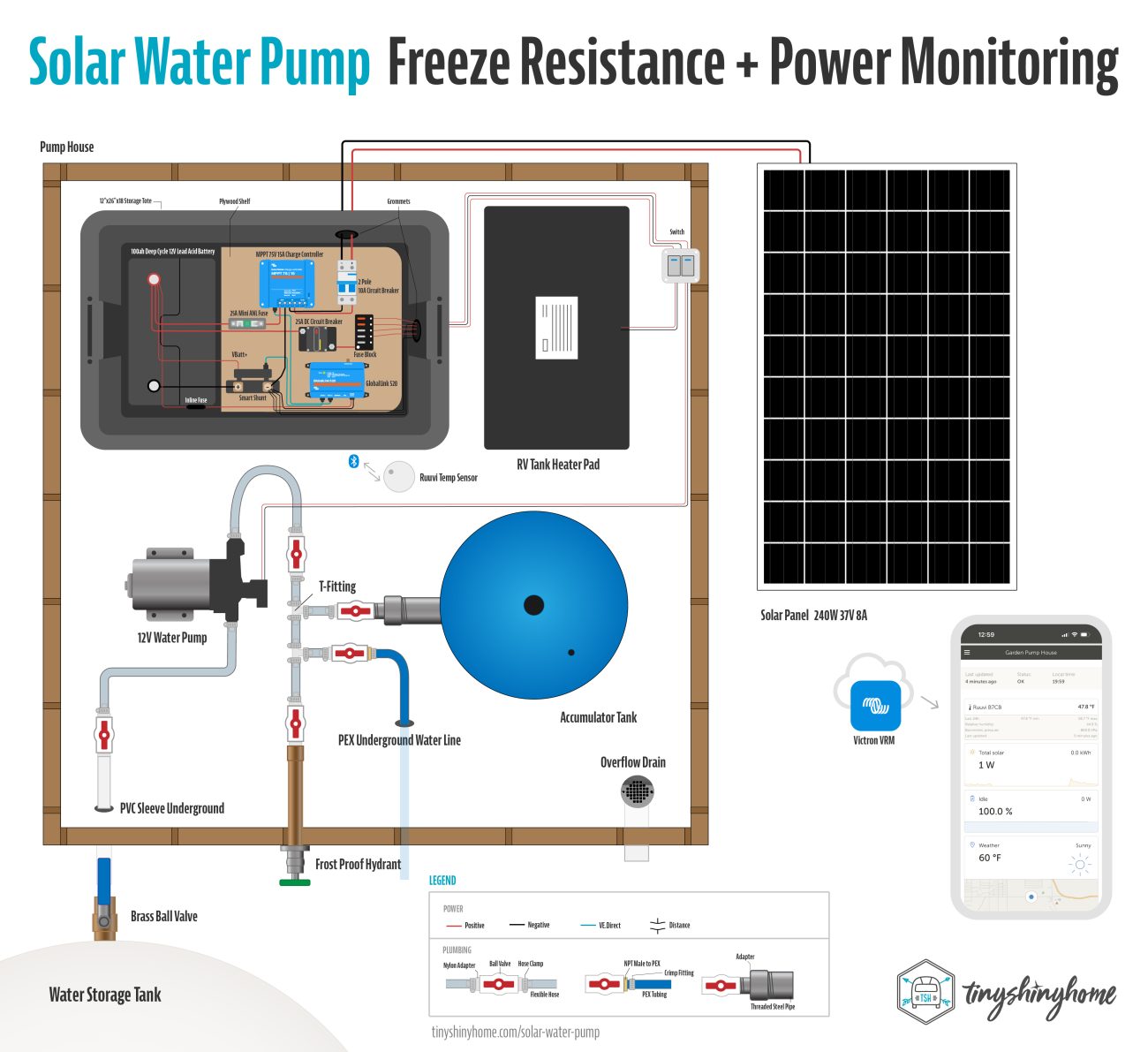
Solar Pump House Option 2: Freeze Resistance + Power monitoring
Some of the very first upgrades we did to our pump house centered around freeze protection. Even though we live in the desert, we are at 5,000 feet elevation, and have seen temperatures in the single digits. Even snow!
We’re always thinking about how we can design things on our property that don’t require a lot of mental overhead. This is a great example of that - do you really want to have to remember to drain your pump house every time it’s going to freeze overnight? Yeah me either.
So we’re going to tackle this in several ways:
- Better Insulation
- Low Power heating
- Temperature monitoring & notifications
- Frost proof spigots
Plumbing
You can use the plumbing steps from the first pump house with a few important changes - we’ll focus on that first, then move into the electrical which is an entirely new setup.
A simple way to protect against freezing is just to add more insulation. So maybe build your walls with 2x6’s so that there’s a bigger cavity to fill. That means you get a higher R-value with more insulation.
Your weak points are always going to be where the water is closest to the elements. So earlier we said our water spigot was the most vulnerable. This is because the ball valve is right where the handle is. If that freezes, the water expands, and you can get a crack in your ball valve. Yes, this has happened to us.
An easy way to fix this is to install a long frost free sillcock on the pump house. These work by moving the opening/closing valve further inside the building. You can buy them in different lengths - we always get them at least 8”-12” long to make sure they are as far away from the cold weather as possible. When you turn them off, the valve closes inside the structure, and it’s slanted so that excess water drains out.
Water coming from the tank can also be run underground below the frost line, and insulated on it’s way up through the floor. Keep in mind that the connection at the tank may need protection as well depending on your climate. So far all we’ve ever needed is a water box with some foam insulation, but you may require better insulation.
Electrical
From here we can start getting a little more nerdy. With an upgraded power system that monitors usage and temperature, we can add additional low power heating elements, keep track of our battery’s voltage, and even setup alarms that can notify us of freezing temperature inside the pump house no matter where we’re at.
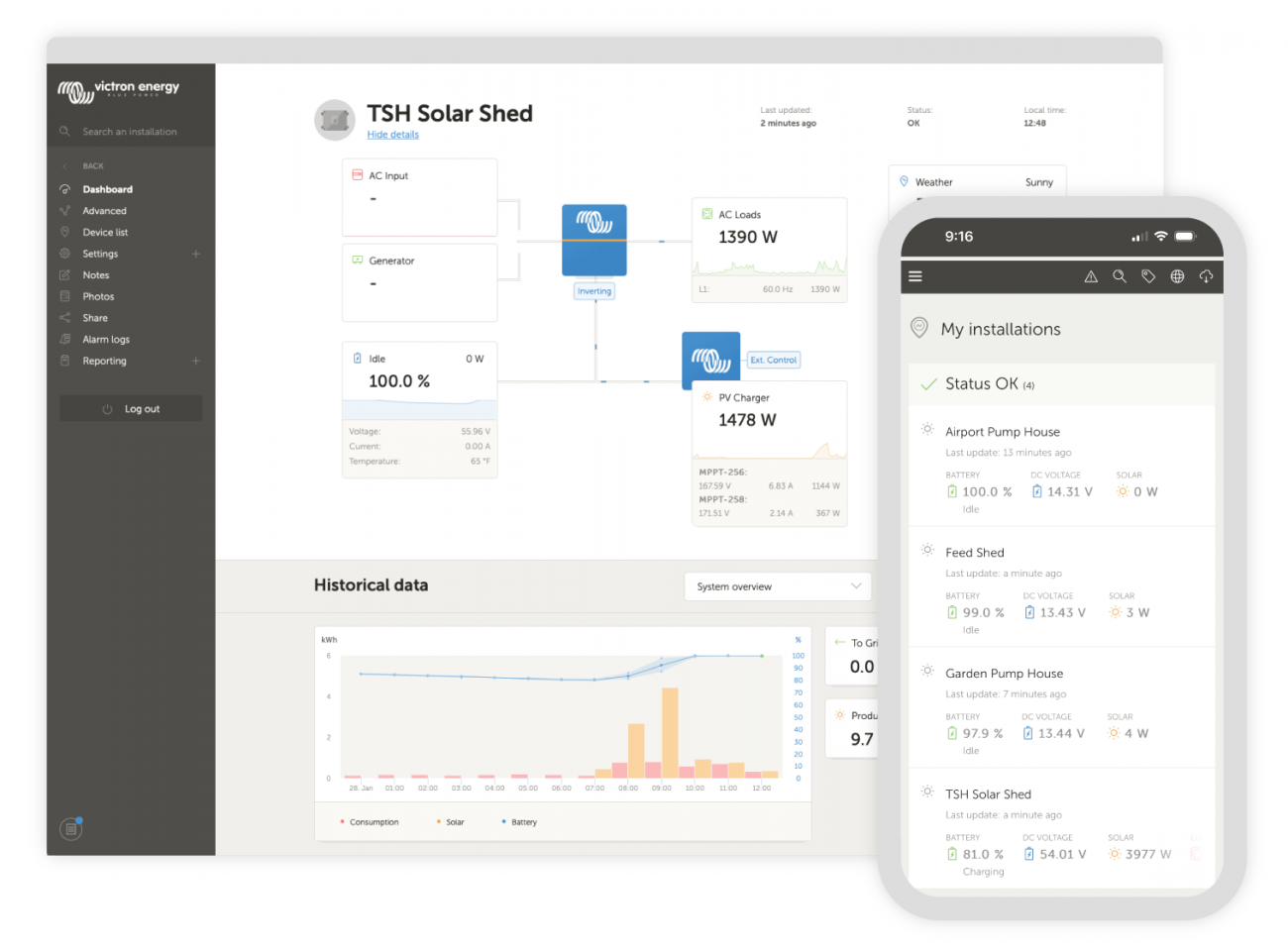
We’ll be utilizing Victron’s excellent VRM portal to enable detailed remote monitoring - we’ve found that their products are rock solid, and their software is well designed, provides deep levels of customization and reporting, and continues to have active development unlocking new features.
Here are the basic building blocks of a small Victron Power System:
- Battery Storage - 12V 100AH Deep Cycle Lead Acid Battery. These are easy to grab pretty much anywhere, fairly inexpensive, and resistant to the wild temperature swings we can get here in the high desert. They’re tough and don’t need fancy BMS’s or special protections.
- Solar Panel - While a small 100W panel is big enough for this size system, we've been using these 240W Santan Solar panels instead because they're so cheap.
- Smart Solar Charge Controller - Since we’re sticking to the Victron Ecosystem, the Smart Solar 75V/15A is the perfect size for the 240W panel without breaking the bank. If you stay with the smaller 100W panel you can use the Smart Solar 75V/10A.
- Smart Shunt - In order to relay data about the battery’s state of charge, the Victron Smart Shunt quickly connects to the battery while also having a data connection port.
In addition to these, you’ll also need a GX device from Victron that will serve as the central “brain” for the system. Then you have to have a network to connect the GX device to so it can push the data up to the cloud. So the first hurdle here is obviously internet connectivity. For any of this notification stuff to work, your pump house will need access to the internet.
You have a few options:
- The Wi-Fi or ethernet based Cerbo-GX is the most powerful brain you can get. You can even add an LTE antenna for connectivity - but this increases the cost, and you have to pay for the plan from your carrier that would give you access.
- The cell based GlobalLink 520 comes with a 5 year LTE-M plan, and gives you a simpler way to connect and monitor the system.
We have a really nice fiber internet and Wi-Fi Mesh setup now, but when we built our first pump houses there was no internet out here. So we opted for the GlobalLink 520. Thankfully the LTE-M network is pretty extensive, but you should double check to make sure there's coverage in your area.
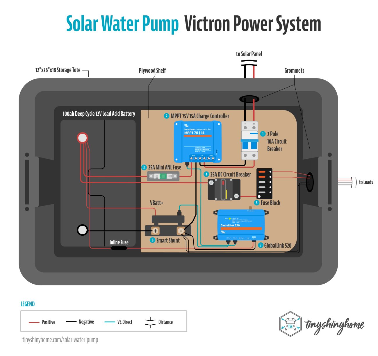
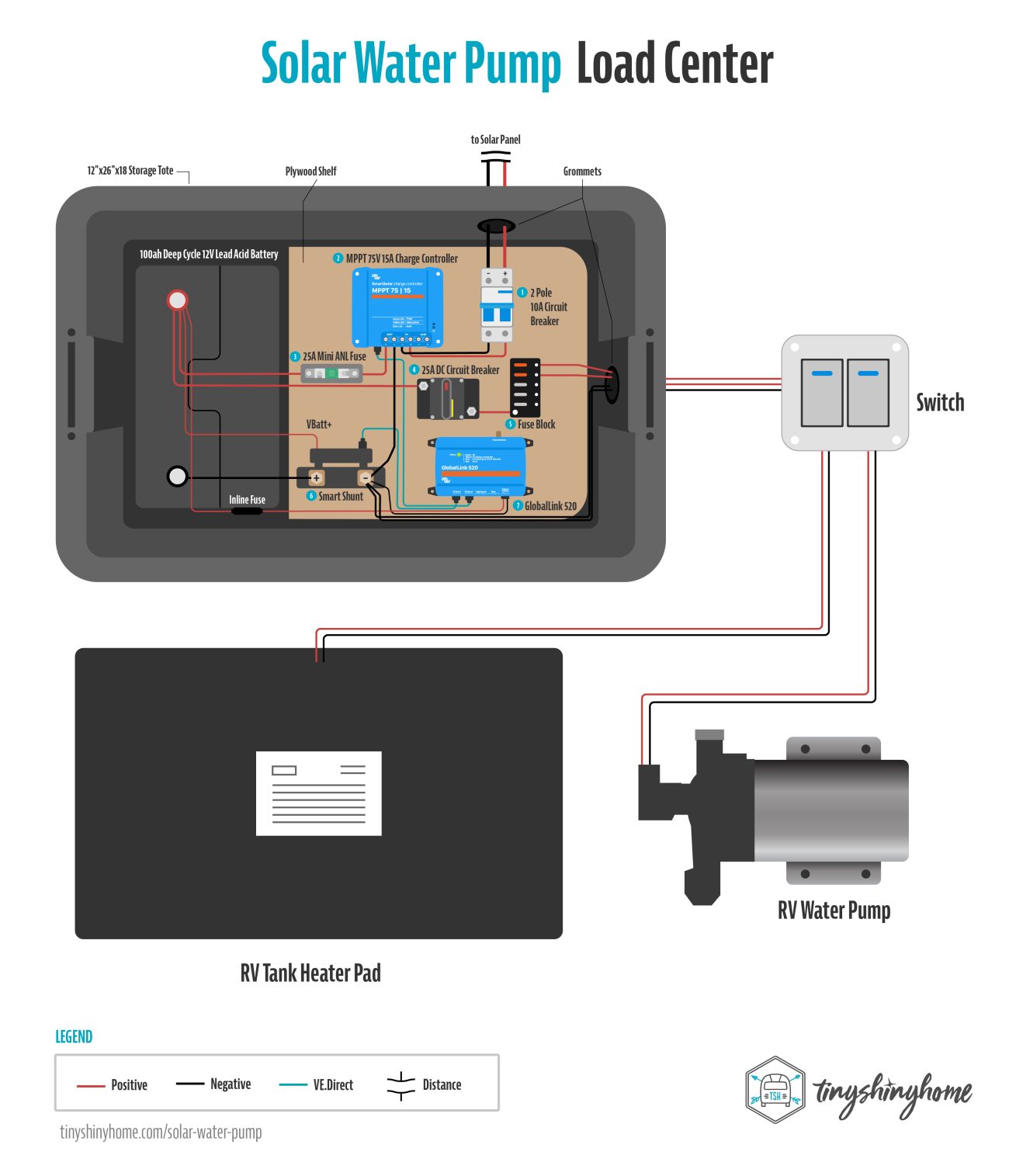
This wiring diagram will use the GlobalLink 520 - but just know you can switch it out for the Cerbo if you already have Wi-Fi or ethernet available. We’ll show Cerbo connections in the 3rd pump house setup.
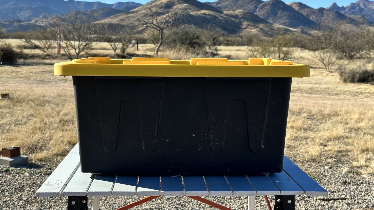
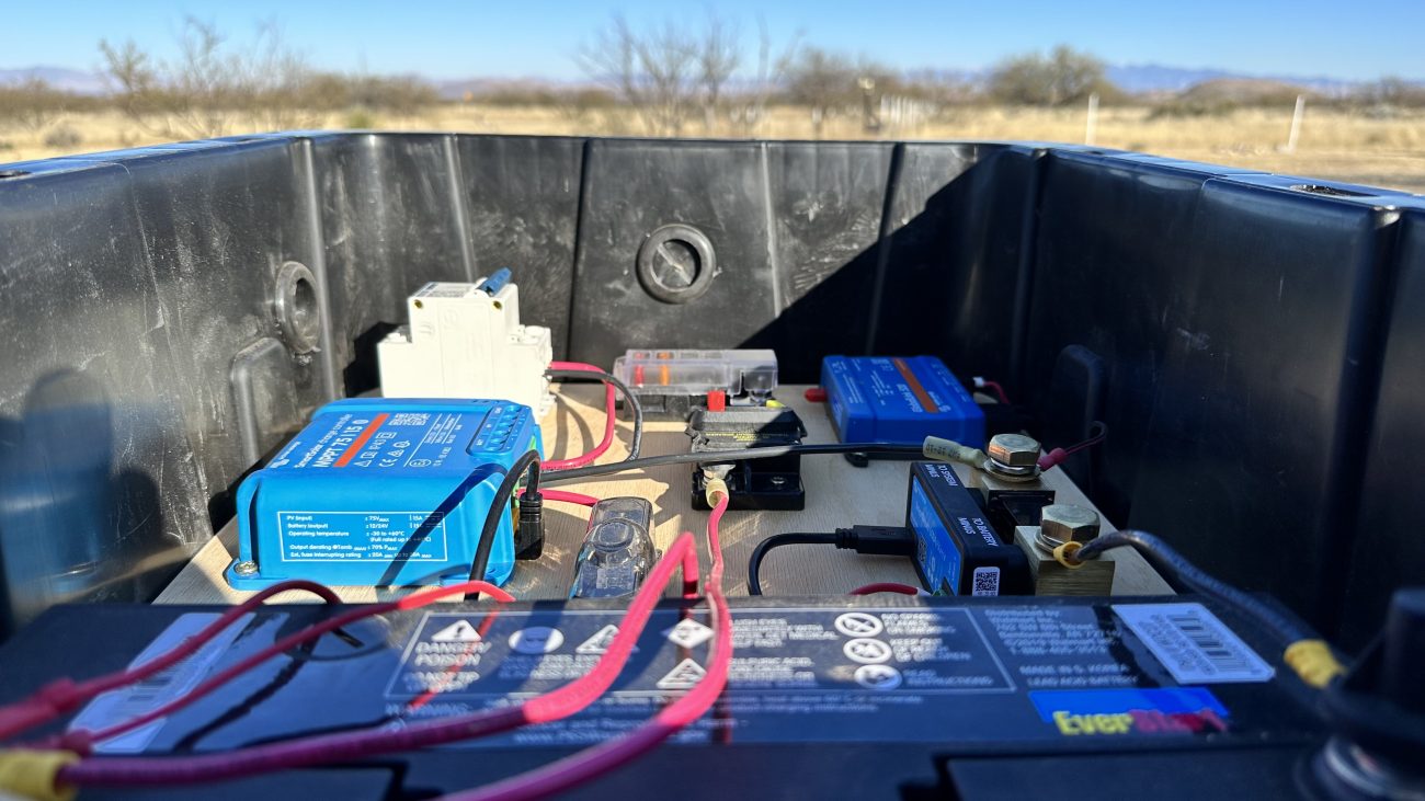
I like to keep these more sensitive electronic components protected. Turns out these plastic storage totes from the hardware store are a great off the shelf solution that don’t cost much. A 12"x26"x18" bin is the perfect size to put your battery and a few pieces of scrap wood for a mounting everything to for easy access.
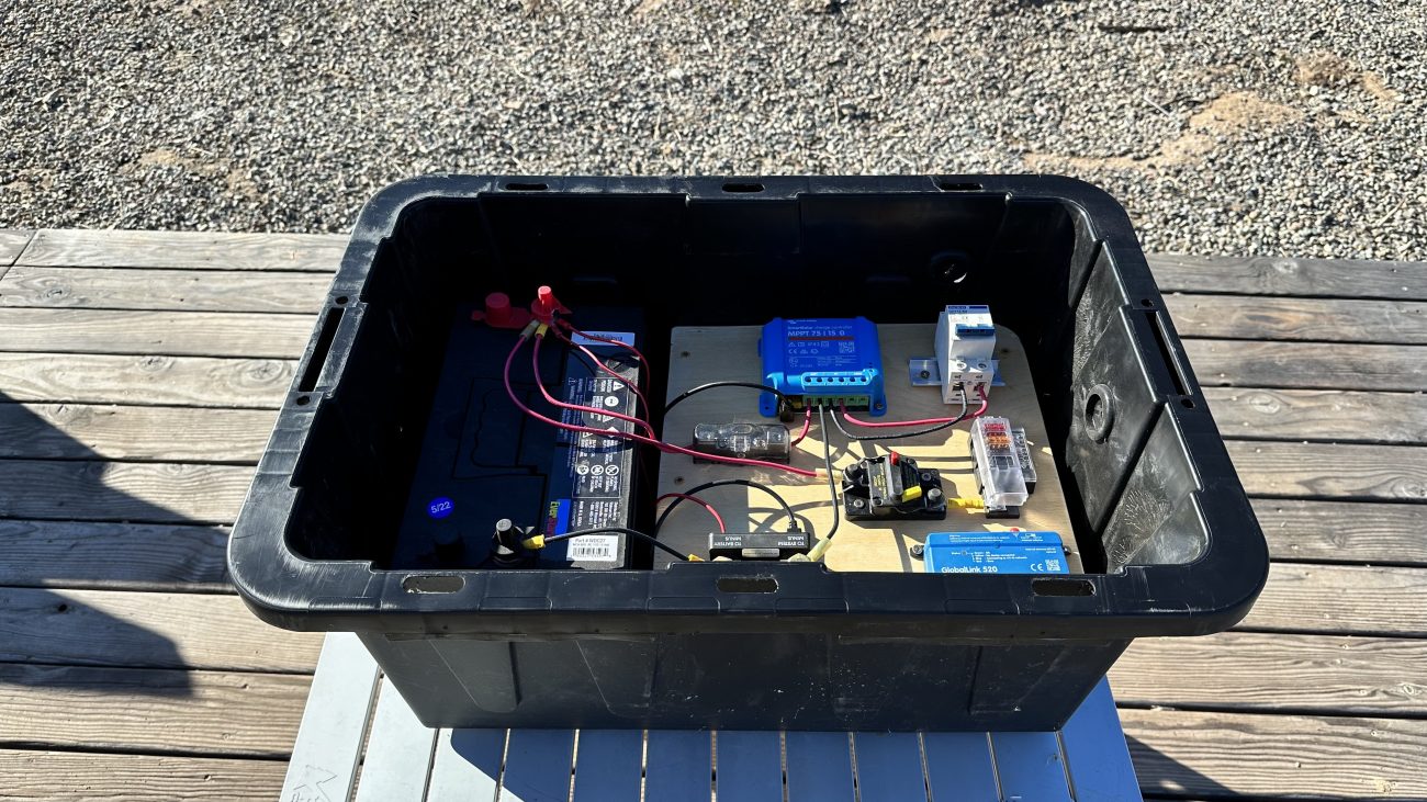
The walls are thin and easy to drill through to install rubber grommets to run wires through, and while they aren’t water or air tight, they do provide considerable protection for everything. Plus since the lid isn’t sealed, the battery can still vent. If you want to add more venting, it’s easy to cut a hole in the side and add your vent of choice.
This allows you to put everything except the solar panel in the box, carry it wherever you want, then run the wires in when you’re ready.
FYI, I’m going to try to walk you through the setup process here as quickly as possible, but if you have more questions we do have a more detailed article and video explanation of this power setup that you can check out.
Warning!
We're officially moving into the "wiring everything up stage." Please keep a few things in mind:
- While connecting your system make sure everything is off. The breakers in the combiner box, all toggle switches, the battery, etc…
- Do your best to run all positives together and all negatives together so that you’re completing the circuit at the last step.
- ALWAYS cover your battery posts so you don’t short anything with an accidental tool drop.
- Make your connections and we’ll go through the boot up process at the end.
I wish each connection was consistent, but you’ll be encountering everything from crimp on ring connectors to spade or butt terminals to screw clamps. I recommend having wire strippers, crimpers, screwdrivers, and a box of connectors on hand.
We mentioned earlier we were using a 240W used solar panel from SanTan Solar. It runs at 37V/8A and PV wire is usually 10AWG.
Step 1 - You want to start by running the PV positive and negative wire to a 2 Pole 10A Circuit Breaker. This is to protect the charge controller from any spikes coming from the panel.
Step 2 - From the breaker we go to the positive and negative PV in connections on the Victron Smart Solar MPPT 75V/15A.
Step 3 - Coming out of the charge controller, the positive wire runs through a 25A Mini ANL Fuse and cover to the positive post of the battery.
This is an additional source of protection for the battery from any spike that might come from the charge controller.
Step 4 - From here we come off the positive post of the battery through a 25A DC Circuit Breaker.
Step 5 - Then we add a small fuse block or load center. This will allow us to isolate each item we want to connect and fuse them individually.
Now for the rest of the Victron Gear.
Step 6 - The Victron Smart Shunt connects its battery minus side directly to the negative post of the battery. The system minus side is where all other negative wires will connect together. There’s also a VBatt+ wire that connects directly to the positive battery post.
Step 7 - Finally, the GlobalLink 520 is hardwired directly the positive and negative posts of the battery so it always has power. At this point you can also connect the Solar Charge Controller and Smart Shunt to the GlobalLink with VE.Direct cables so they all start talking to each other.
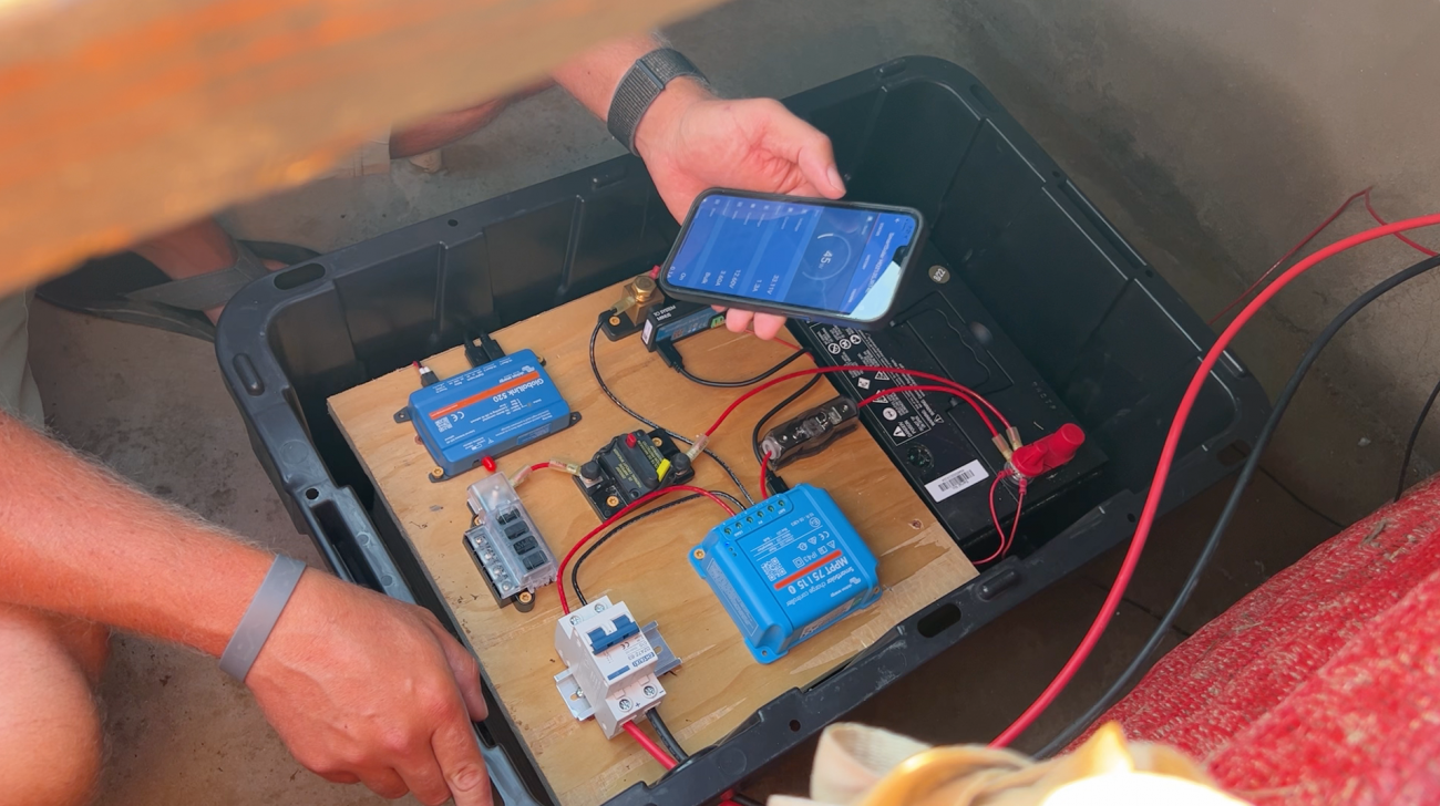
At this point the GlobalLink and SmartShunt should be on - you’ll want to install your ANL fuse so the charge controller can turn on as well.
Before we connect any loads, let’s tweak our settings on the Victron components. The easiest way to change settings is to use the Victron Connect App on a smartphone or tablet. This is done via Bluetooth so you just have to be close by and you’ll see the option to connect.
These are generic 12V lead acid settings - make sure to check with your manufacturer if these settings should be different for your battery.
VICTRON SMART SHUNT SETTINGS
First, we want to tell the system the voltage and capacity we’re dealing with. In our case that meant:
- Battery Capacity: 100Ah (or whatever AH your battery is)
- Charged Voltage: 13.2V
We didn’t feel the need to change any of the other settings and left them as is.
VICTRON SMART SOLAR MPPT 75V/15A SETTINGS
Then we want to tell the charge controller how to charge the battery.
- Battery Voltage: 12V
- Tap “User Defined” for Battery Preset
- Absorption: 14.3V
- Float: 13.4V
- Equalization: 14.3V
The rest of the settings we left as is.
VICTRON GLOBALLINK 520 SETTINGS
Finally, we need to connect this device to our Victron VRM Portal. If you don’t already have a VRM account, make sure to create that first. Then click “Add Installation” and choose the GlobalLink 520 Icon.
It’s going to ask you for the VRM Portal ID that is located on the back of the GlobalLink. It might be on the box as well, but learn from my mistake and take a picture of this number before you do your full install.
Pop in that number, give it a name, and as long the GlobalLink is connected to the LTE-M network, you should see it load in your VRM. That’s it!
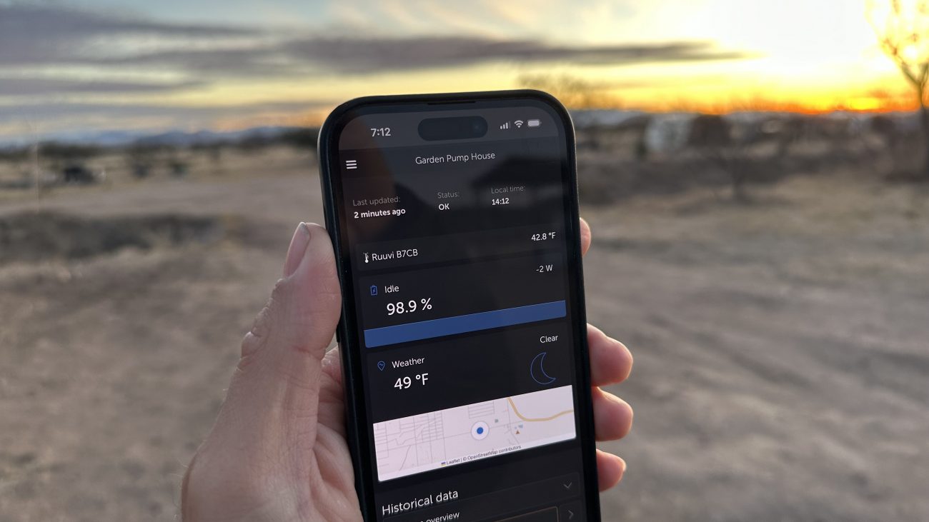
To keep data usage low, the GlobalLink updates every 15 minutes, and you’ll see your solar input wattage and battery state of charge. And now that you’re connected to the VRM you can setup your own custom alarms and notifications or turn on custom widgets and run reports.
We’ll get to that in a minute. But first let’s run our loads. We’ll be upgrading this setup by adding an RV tank heater and a switch for easy access to power loads on and off.
The biggest difference between this and the 1st pump house is that now we have a load center. This means we’ll be connecting the positive wire from each appliance to an individual spot on the load center and then adding the proper sized blade fuse (1.25x the max amperage it should draw). The negative wire for each appliance will go to the system minus side of the Smart Shunt.
The benefit of adding the breakers and fuses to this system means you’re protecting everything more intelligently, creating easy ways to shut off power to individual components for maintenance, and building a safer system less prone to overheating or fire.
I like to add an exterior switch on the outside of the structure to quickly turn off the pump or heater without opening everything up. This can be done by running the positive wires from each fuse to the switch of your choice, a negative wire back to the smart shunt, and then connecting both positive and negative wires from each appliance to the switch.
The switch you use should be rated for the appliance you’re powering. So if you are using an 8A water pump and a 5A tank heater the switch should handle at least 15A.
So in case I lost you there - the pump positive wire should go through the switch to its own connection on the load center. The negative wire should go to the switch and continue to the Smart Shunt. Same for the tank heater.
The jury’s still out on whether the tank heater pads actually do their job, but theoretically they should come on when it gets cold and provide some warmth near your water lines.
The final step with the power system is to complete all the circuits. So install your individual blade fuses for each appliance, and flip on the 25A Circuit Breaker. If you installed a switch, now is the time to turn it on and make sure things are working.
Finally, flip the 2 Pole 10A circuit breaker and confirm that the solar panel is charging the battery. This is easy to see in the Victron app or VRM.
Now that the base system is working it’s time to setup temperature monitoring and notifications.
Wireless Temperature Sensor
If you’re using the GlobalLink 520 you’ll need a wireless sensor - the Ruuvi Humidity and Temperature works perfectly in the Victon ecosystem.
Download the Ruuvi app on your phone (iOS or Android), then pull the plastic battery stopper out, and find the device via the app. Here you can setup some settings, and give it a name - but really what you are doing is activating it so that the GlobalLink can see it.
Now go place it near your GlobaLink. Open the Victron Connect App on your phone, and connect to the GlobalLink. Go to Settings > Smart Devices and wait a minute for the Ruuvi Tag to show up.
Activate it, and that’s pretty much all there is to it. You’ll need to wait until the VRM refreshes to see anything (remember, it updates every 15 minutes) - but then the temperature sensor will show up on your dashboard.
To create custom notifications, go into that installation in the VRM, Settings > Alarm Rules. Select “Add New Alarm Rule”, choose the Ruuvi Tag as the device, then the Temperature parameter, then set your specific amounts on the next screen.
Something like this should work:
- Low: 33
- Clear low alarm above: 35
- High: 120
- Clear high alarm below: 119
Then just make sure you have your notification settings turned on to deliver via email or push on your phone. Fancy!
This is a great way to get ahead of potential problems. You could even set your temp notification to 40 if you really wanted to make sure you knew when it was getting close. That’s what’s so cool about Victron’s setup - you get to build and design exactly what you need.
Solar Pump House Option 3: High End Permanent Installation
Temporary pump houses are a vital part of building raw land from scratch, but eventually you’re going to settle into something more permanent. This happened for us when we finally moved our Airstream to its permanent parking spot under a metal truss cover.
We used this opportunity to re-think a lot of what we had learned and add some important upgrades.
- Permanent concrete floor
- Filtration system for hard water
- Shutoff Loop for maintenance
- High Flow Pump for Additional Fixtures
- AC Power Backup
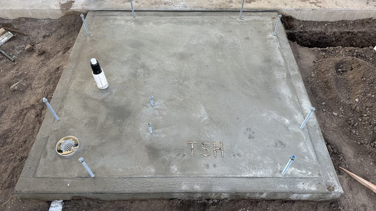
One of the best things you can do to make your pump house more permanent is to pour a concrete pad for the floor. This allows you to create a clean separation from the ground, and a much nicer surface to work with when building out the inside.
A few things we recommend:
- Add in J-Bolts around the perimeter for your framed walls to attach to
- Build in an overflow drain in case something leaks
- Stub up insulated pipes to for underground water input or output later
The inside is very similar to the pump house option 2 with a few changes.
Plumbing
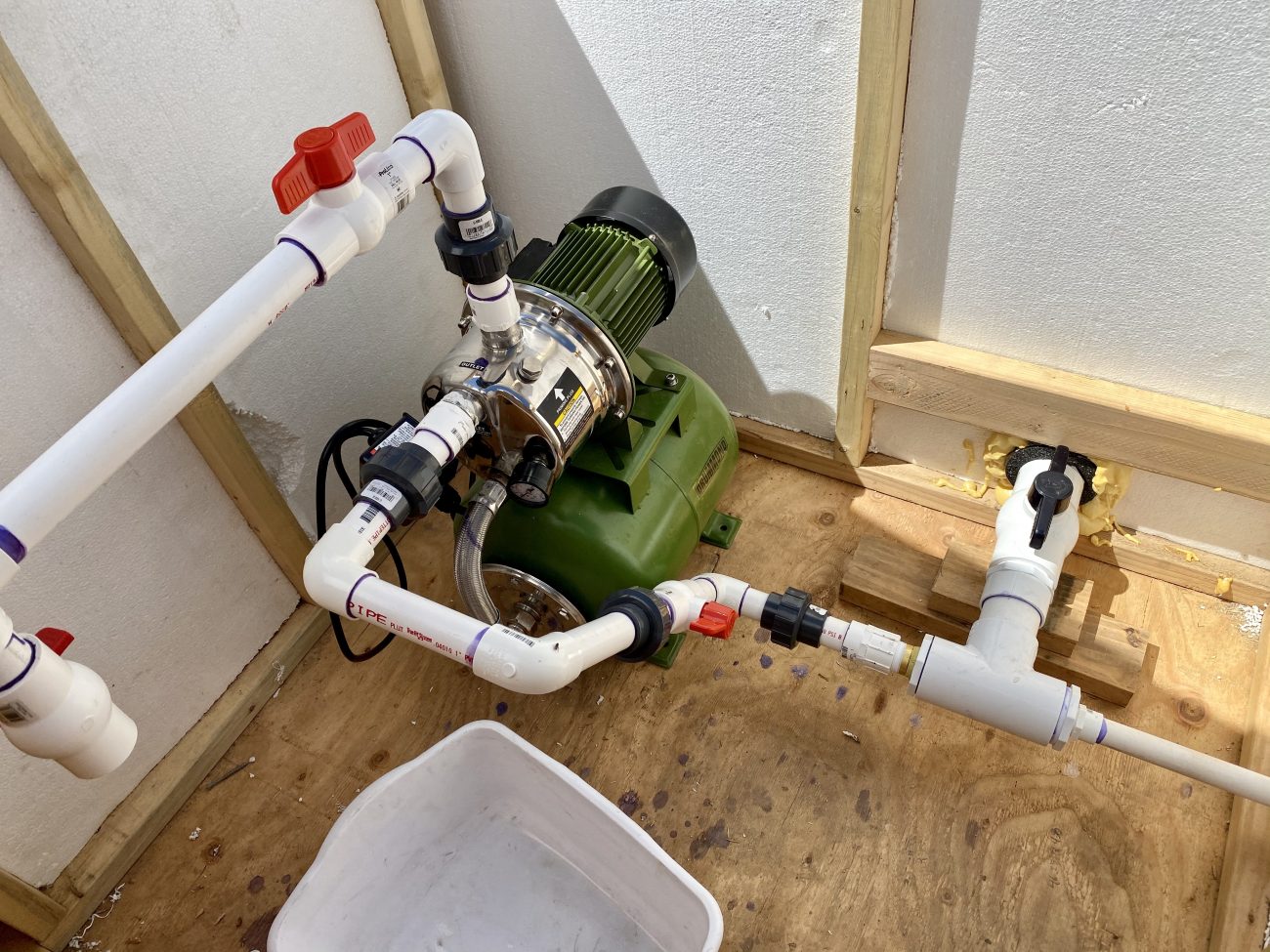
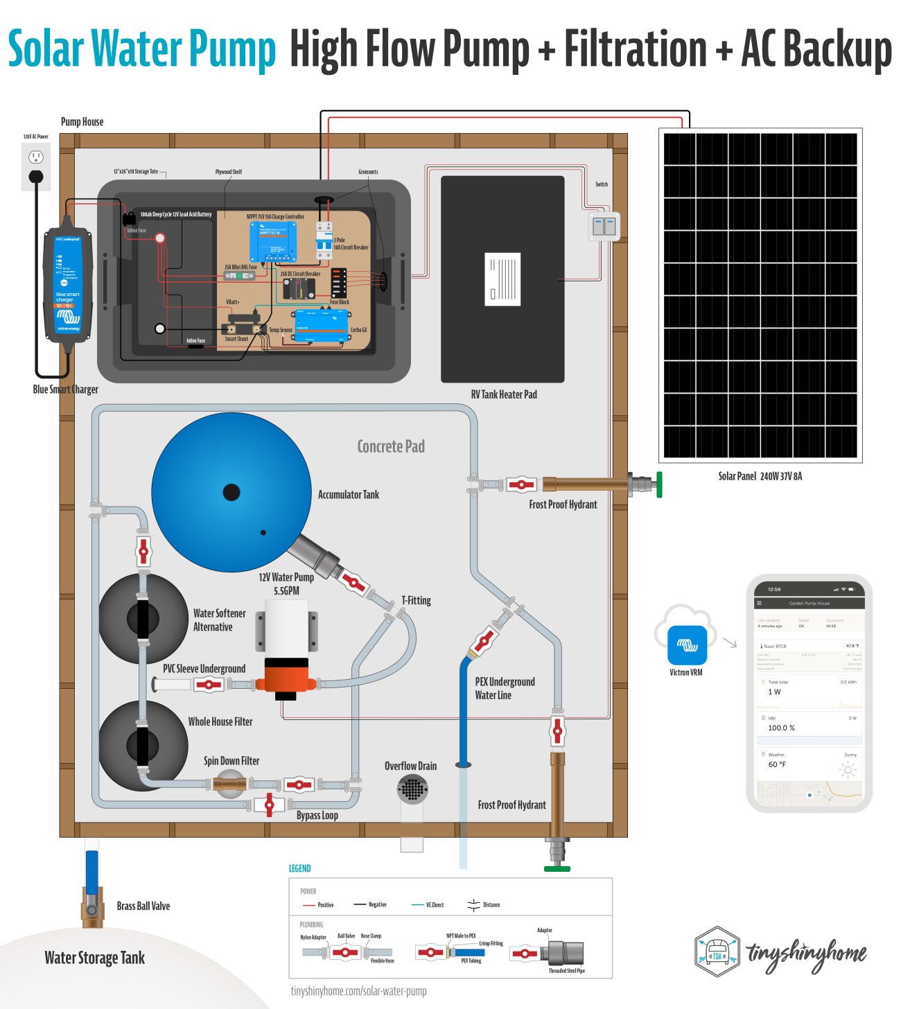
The first upgrade that you can add is a higher capacity pump. The Seaflo 55 Series Diaphragm Pump gives you 5.5 GPM to run multiple things at a time. So if you’re getting a shower and trying to wash dishes at the same time it’s not as noticeable. We’ve found the higher flow pump to be super helpful at our irrigation pump where we’re drip irrigating long distances, too.
However, the increased amperage demand from this larger pump can be problematic for small 12V systems so unless you really need it I’d just stay with the smaller 3.5GPM pump. If you decide to upgrade the pump here’s what you’ll need to do.
Plumbing-wise not much will change. Use the same fittings to slide the 1/2” flexible tube on, and wire in the positive and negative. The only thing you really have to watch out for is that this pump will use a lot more power.
This Seaflo pump can max out at 17A which means you need to upgrade your blade fuse to 25A, and make sure the switch is rated for the additional load. If your wires are long, you may need to increase the gauge size as well. Always double check and use a wire sizing calculator to make sure (and keep in mind the length includes positive and negative wires so double the physical distance).
Oh, and the pressure tank needs adjusting as well. For this 5.5GPM pump set it to 15-16 PSI.
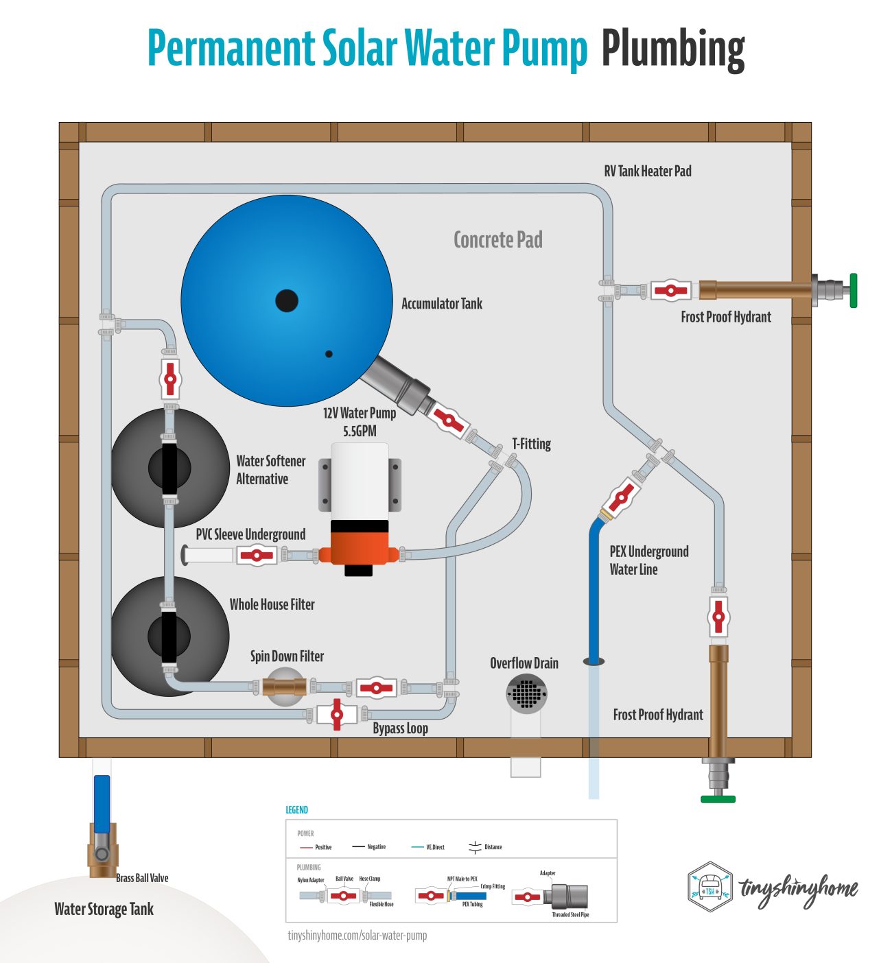
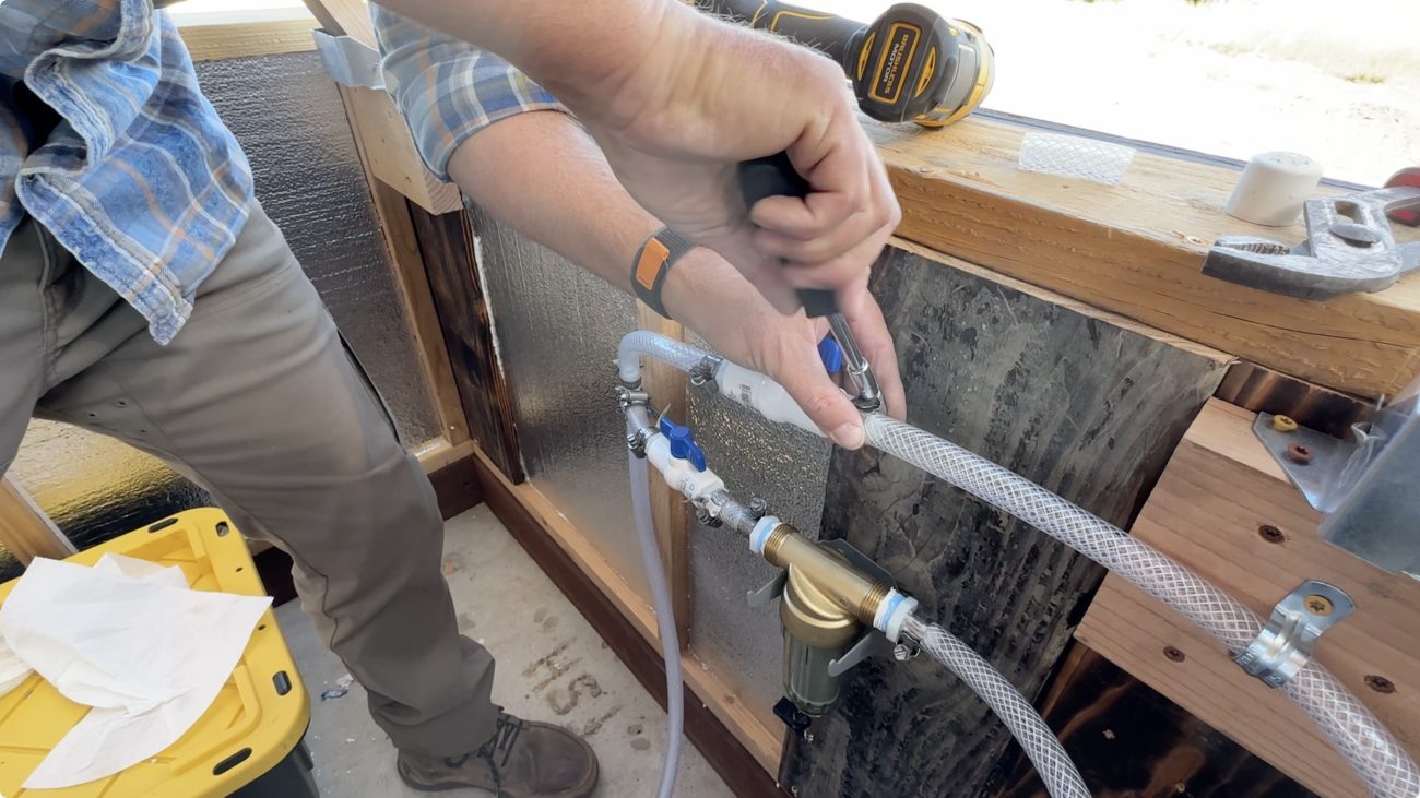
Next we’re going to add in filtration and descaling. We catch as much rainwater as we can, but sometimes have to haul water in from a local well share. We’ve noticed it’s very hard water, and clogs up our shower heads and sink faucets.
So out of the pump we’ll still go to the pressure tank first, but immediately tee off to the filters and bypass loop.
The idea is that we want all the water to pressurize, then be filtered before going out to any of the spigots. But also we want a way to easily bypass the filters whenever they need to be replaced or worked on.
Coming out of the pressure tank use another 1/2" Nylon Barb Tee to start the loop. On one side will be a ball valve that stays closed during normal operation.
On the other side is another ball valve that begins the filtration. First is a spin down sediment filter - this will collect any large sediment, and help the filters last longer. Note that you’ll need 3/4” Male NPT to 1/2” barbs on each side. Then you can use something like the AO Smith Whole House Filter combined with their Salt Free Descaler to ensure better quality water coming into your house.
Both of these use the larger 3/4” Male NPT to 1/2” barbs on each side, and you do want to follow the instructions for flushing before installing. So the order is:
- Spin Down Sediment Filter
- Whole House Filter
- Descaler
On the output of the descaler add another ball valve, tee back into the line, and that completes the bypass. When you need to replace these filters simply shut off the ball valves at the beginning and end. If you need water while you’re working turn on the bypass ball valve. Easy!
From there you just run your 1/2” Flexible Tube to whatever fixtures you like - through the wall of the pump house, underground to somewhere else - whatever works for your specific setup.
Electrical
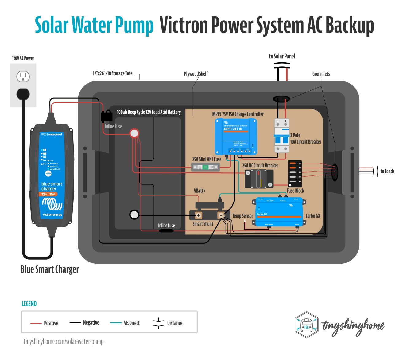
Finally, we’ll explore a different way to keep tabs on your temperature, and add AC backup.
The last pump house recommended the GlobalLink 520 under the assumption that you may not have fully functioning internet setup on your property yet. But by the time you are ready to build a more permanent pump house, you might.
So in this example we’ll switch out the GlobalLink for the CerboGX. The benefit here is that you can connect it directly to Wi-Fi or ethernet, and use a simpler hardwired temperature sensor instead of the wireless Ruuvi.
You’d still connect your charge controller and Smart Shunt to the Cerbo via VE.Direct Cables, and use the temperature input to connect the sensor. Programming the notifications works the same, you just choose the new sensor and input your values.
You might be thinking by this point - if this is a more permanent install why go through all the trouble of this complicated solar system, with batteries and shunts and everything else? Great question - you could totally just run 120V power, get an AC powered pump to simplify this whole setup.
We’ve actually done this in some more recent buildings where the water isn't as critical.
However, if you’d prefer your pressurized water to not depend on your main power system, then keeping the 12V setup is a good way ensure you always have water during a power outage, and you can make it even more reliable by adding an AC charger. Redundancy is good.
Everything stays the same except we add a Victron Blue Smart IP65 Charger that plugs into a standard outlet and connects directly to the battery to keep it topped off.
We’ve found that with the larger 5.5 GPM pump, having the AC backup really helps as its large amperage draw can pull the battery voltage down if it runs too long filling up the pressure tank. It can get stuck on an endless loop of trying to reach pressure to shutoff, but not being able to because the battery voltage is too low. Then the battery dies.
The more I’ve used this 5.5GPM pump I’m convinced it should only be made as an AC pump. The crazy high amp draw just puts too much strain on a 12V system.
Good news is that by adding the AC charger it’ll not only keep the battery topped off all the time, but can augment the battery and solar charger to ensure the pressure is always reached quickly.
The Charger comes in several options and sizes - we went with the 12V 15A version, and kept it on the default settings. Connect the negative line to the SmartShunt for more accurate readings of power coming in.
And there you have it - the fanciest solar pump house you ever did see.
Now don't forget - all of these options are just suggestions. You can take ideas from pump house 1, 2 and 3 and make your own creation. That's the beauty of a modular system like this!
Shopping List
Since your setup will likely be slightly different than options above, I'm going to group links to items you can buy to assemble by type. You'll have to study the diagrams and decide which pieces you need and how many of each. Most of these are affiliate links.
Note: Plumbing is notoriously finicky so there's a good chance you'll need to source additional fittings from your local hardware store to make certain connections work. In fact, I'd recommend getting all your PVC and steel fittings form the hardware store. The nylon hose barbs are much harder to find in the quantities you need, though. Order them online.
Basic Pump & Connections
SHURFLO 1/2” FPT x 1/2” Barb Straight Wingnut Swivel Adapter
1/2” Nylon Hose Barb x 1/2” Male NPT (you'll need a lot of these)
Miniature All Stainless Worm Gear Hose Clamp, 5/16” - 7/8” (you'll need a lot of these, too)
PEX & Underground Plumbing
1/2" PEX Tubing (you may need more depending on your run)
Basic Electrical
10-12AWG w/ 3/8" Ring Terminals (you might need extra)
Upgraded Plumbing
Note: We recommend buying Victron gear from a local authorized dealer that can actually support you long term.
Upgraded Mini VRM Electrical
Ruuvi Temperature Sensor or Victron Temp Sensor (if you get Cerbo GX)
Upgraded Pump & Filters
Wrapping it Up
Whew! I’m not sure how I keep talking myself into writing these massively detailed posts, but here we are again.
I hope these hard fought plumbing and electrical tips give you a better understanding of how to build your own simple (or complex) solar powered water pump house.
If you found this interesting we’re just getting started here on our off-grid homestead. Besides building all sorts of unique, sustainable structures we're always working on some kind of rainwater catchment, off-grid solar, or permaculture project. There's so much going on, and we’d love to share it with you! Make sure you’re subscribed so you don’t miss our next project.
Until next time!
Build Your Own Off-Grid Pressurized Water System!
Want to save this article and video for later? Our detailed walk-through & planning guide will help you design & build 3 different solar powered pressurized water systems for remote off-grid applications.

Apparel
Grab a fun, comfy t-shirt & help support our family.


About the Author
Jonathan Longnecker is the strongly opinionated tattooed and bearded half of Tiny Shiny Home. He loves making music, figuring out nerdy solutions, exploring the outdoors, and living off-grid.
comments powered by Disqus